Iranian Classification Society Rules

< Previous | Contents | Next >
SURVEY PLANNING QUESTIONNAIRE 
The following information will enable the Owner in co-operation with the Society to develop a survey programme complying with the requirements of the Rules. It is essential that the Owner provides, when
completing the present questionnaire, up-to-date information. provide all information and material required by the Rules.
The present questionnaire, when completed, is to
Basic information and particulars
Name of ship : | |
Class No. : | IMO No. : |
Class Notation : | |
Flag State : | |
Port of registry : | |
Gross tonnage : | |
Deadweight(metric tones) : | |
Length between perpendiculars(m) : | |
Shipbuilder : | |
Hull number : | |
Date of delivery of the ship : | |
Date of build / major conversion : | / |
Owner : | |
Thickness measurement company : | |
Owner's representative :
Signature
Name
( Place / Date )


Guidance Relating to the Rules for the Classification of Steel Ships 2015 117
Pt 1 Classification and Surveys
Annex 1-3 Example of the Survey Programme and the Survey Planning Questionnaire Pt 1, Annex 1-3
![]()
SURVEY PLANNING QUESTIONNAIRE
1. Information on access provisions for Close-up Surveys and thickness measurement
The Owner is to indicate, in the table below, the means of access to the structures subject to Close-up Survey and thickness measurement. A Close-up Survey is an examination where the details of structural components are within the close visual inspection range of the attending Surveyor, i.e. normally within reach of hand.
Hold/Tank/ Space | Structure* | C(Cargo)/ B(Ballast) | Access provisions | |||||
Permanent Means of Access | Temporary staging | Rafts/Boats | Ladders | Direct access | Other means (please specify) | |||
* Each structural components which have different type of access provisions are to be specified.
(e.g. Fore peak/Aft peak/Under deck/Side shell/Bottom transverse/Longitudinal/Transverse/Hatch side coamings/Topside slopping plate/Upper stool plating/Cross deck/Side shell, frames & brackets/Transverse bulkhead/Hopper slopping plating/Lower stool/Tank top/Double bottom structure/Upper stool internal structure/Lower stool internal structure, etc.)
![]()
History of bulk cargoes of a corrosive nature(e.g. high sulphur content) /
![]()
History of cargo with H2S content or heated cargo for the last 3 years together with indication as to whether cargo was heated and, where available, Marine Safety Data Sheets(MSDS)*


![]()
* Refer to resolution MSC.150(70) on Recommendation for material safety data sheets for MARPOL Annex I cargoes and marine fuel oils.
118 Guidance Relating to the Rules for the Classification of Steel Ships 2015
![]()
Pt 1 Classification and Surveys
Annex 1-3 Example of the Survey Programme and the Survey Planning Questionnaire Pt 1, Annex 1-3
![]()
SURVEY PLANNING QUESTIONNAIRE
2. Owner's inspections
Using a format similar to that of the table below (which is given as an example), the Owner is to provide details of the results of their inspections for the last 3 years on all cargo holds/tanks, ballast tanks and void spaces within the cargo (length) area, including peak tanks.
![]()
Hold/Tank/Space Use
Corrosion
![]()
prevention system (1)
Coating extent (2)
Coating condition (3)
Structural deterioration (4)
Hold/tank/space history
(5)


![]()
(1) HC=hard coating,
(2) U=upper part,
(3) G=good,
SC=soft coating, M=middle part, F=fair,
SH=semi-hard coating, L=lower part,
P=poor,
NP=no prevention C=complete
RC=recoated(during the last 3 years)
(4) N=no findings recorded,
Y=findings recorded, description of findings is to be attached to the questionnaire
(5) DR=damage & repair, L=leakages,


CV=conversion(description is to be attached to the questionnaire)
Owner's representative :
Signature
Name
( Place / Date )
Guidance Relating to the Rules for the Classification of Steel Ships 2015 119
Pt 1 Classification and Surveys
Annex 1-3 Example of the Survey Programme and the Survey Planning Questionnaire Pt 1, Annex 1-3
![]()
SURVEY PLANNING QUESTIONNAIRE
3. Reports of Port State Control inspections
![]()
![]()
List the reports of Port State Control inspections containing hull structural related deficiencies and relevant information on rectification of the deficiencies:


![]()
4. Safety Management System
![]()
List non-conformities related to hull maintenance, including the associated corrective actions:
![]()


![]()
5. Name and address of the approved thickness measurement company
![]()
Name Address Approved by
![]()


![]()
![]()
120 Guidance Relating to the Rules for the Classification of Steel Ships 2015
Pt 1 Classification and Surveys
Annex 1-4 Owners Inspection Report Pt 1, Annex 1-4
![]()
Annex 1-4 Owners Inspection Report
The Owner of ships subject to the enhanced survey programme such as bulk carriers, oil tankers and chemical tank-
ers, etc. is to complete the Owner Inspection Report and retain it inside the ship, according
103. of the Rules. An example of the Owner Inspection Report is shown in Table 1.
to requirement Ch 3,
Elements | Cracks | Buckling | Corrosion | Coating Cond. | Pitting | Rep., Mod | Other |
Deck | |||||||
Bottom | |||||||
Side | |||||||
Longi. BHD | |||||||
Trans BHD |
Table 1 Example of Owner Inspection Report
Owners Inspection Report(Structural Condition) |
· Deck : ․ Side : · Bottom : ․ Longi. BHD : · Trans. BHD :
· Date : · Result in General :
|
Date of Inspection : Inspected by : Signature : |
![]()
![]()
Guidance Relating to the Rules for the Classification of Steel Ships 2015 121
![]()
Pt 1 Classification and Surveys
Annex 1-5 Thickness Measurement Method for Hull Structural Member Pt 1, Annex 1-5
![]()
Annex 1-5 Thickness Measurement Method for Hull Structural Members
1. General
(1) Purpose of thickness measurement
(A) Corrosion seems to be one of the common denominators in many cases of serious hull cas- ualties resulting in losses of vessels, cargoes and human lives. The purpose of thickness measurement described in the Rules is to prevent vessels from hull casualties. Information provided in the report of hull thickness measurements for a vessel put in service indicates that the vessel is maintaining sufficient local and global strength, if necessary renewal/repair works can be made accordingly. Therefore, thickness measurement reports giving information for the assessment of hull strength(including watertight integrity) as well as for the main- tenance of the hull is to be carefully considered.
(B) Where the ship has been constructed with FRP, aluminum alloy or other anti-corrosion ma- terials, the thickness measurements may be dispensed with.
(2) Extent of thickness measurement
The standard extent of thickness measurements complying with the "Rules for Classification of Steel Ships" is given in Table 4 to Table 13. However, the extent of thickness measurements may be specially considered by the Society, considering the coating and corrosion condition.
(3) Thickness measurement report
(A) The thickness measurement report submitted to the Society shall include the general partic- ulars as shown in Table 19, measuring position, diagram with details of the position to be
measured, original thickness, maximum allowable diminution and present thickness(gauged) and diminution, etc. Reporting form shown in Table 20(or equivalent form) is to be used
for recording measuring position, original thickness, maximum allowable diminution, present
thickness(gauged) and diminution, etc.
(B) The thickness measurement report is to be verified and countersigned by the attending Surveyor, and the record is to be kept in the Society and on board the ship.
2. Wear Limit
(1) General
(A) This annex provides standard of wear limit for decision of repair of main hull structural members. Wear limit or allowable wear quantity means allowable wear limit.
(B) When worn down thickness of hull structural members exceed the wear limit, inspections
are to be carried out in detail and corresponding hull structural members are to be renewed by the date recommended by the Surveyor.
(C) Wear limit provided by this annex is based on the requirements and scantlings during
construction. Therefore, the wear limit for the structural members which have scantlings larger than the required ones and margin in strength may be considered appropriately.
(D) Wear limit on hull structural members not provided by this annex follows what is deemed appropriate by the Surveyor.
(2) Wear limit on hull structural members
(A) Wear limits on structural members are provided in Table 1. However, for vessels built un-
der IACS Common Structural Rules(Pt 11, Pt 12 or Pt 13), Pt 1, Ch 3, 105. 2 of the Rules is to be applied.
(B) Value of wear limit indicates the limit on equally distributed wearing.
(C) When partial corrosion occurs in stress concentrated part, partial replacement or reinforce- ment shall be carried out without reference to Table 1.
122 Guidance Relating to the Rules for the Classification of Steel Ships 2015
![]()
Pt 1 Classification and Surveys
Annex 1-5 Thickness Measurement Method for Hull Structural Member Pt 1, Annex 1-5
![]()
![]()
![]()
![]()
Table 1 Wear limit on members
Local Wear Limit | Name of member | Wear limit | ||
Class 1) | Class 1) | Class 1) | ||
Strength deck plating, sheer strake and longitudinals to these members, shell plating, bottom shell plating, bulkhead plating of deep tank4), topside sloping plating, hopper side sloping plating, inner bottom plating | 20 % of original thickness | (20 % of original thickness) + 1 mm | 1 mm | |
Floor & girder of double bottom, web and face of primary supporting member | 20 % of original thickness | 25 % of original thickness | ||
Effective deck5) plating, superstructure deck plating, deck plating inside the line of cargo hatch openings, watertight bulkhead plating other than bulkhead plating of deep tank, hatch cover(including stiffeners), hatch coaming(including stiffeners), web, face and brackets of secondary stiffener3) | 25 % of original thickness | 30 % of original thickness | ||
Web, face and brackets of frames in cargo hold/tank | 20 % of original thickness or 1.5 mm , whichever greater | 25 % of original thickness or 2.5 mm , whichever greater | ||
Partial corrosion (e.g pitting) | 30 % of original thickness | 35 % of original thickness | ||
(NOTES) 1) For ships classed through the Classification Survey during Construction : the Class I, II and III are as follow. (a) Class I : It is applied to ships having one or two of the following characteristics. (i) Ships, with of length of 90 m and above, which are classed with Classification Survey during Construction in accordance with the Rules after 1st July 1998. (ii) Ships carry for liquid cargo, which are classed with Classification Survey during Construction in accordance with the Rules after 1st July 1998. (b) Class II : Ships, other than in Class I and III. (c) Class III : Ships constructed with steel, which is applied to the Rules for the Classification of High Speed and Light Crafts and the Guidance Relating to the Rules for the Classification of High Speed and Light Crafts. 2) For ships classed through the Classification Survey after Construction, the separate requirements specified by the Society are to be applied. 3) Secondary stiffener refers to the member which is supported by the primary supporting member and does not support another reinforcement member. 4) Definition of deep tank is specified in Pt 3, Ch 15, 101. of the Rules. 5) Definition of effective deck is specified in Pt 3, Ch 5, 103. of the Rules. | ||||
Wear relati ng to the Shearing Strength | The shearing strength evaluation is to be carried out in any of the following cases when the thickness measurement for the longitudinal strength evaluation is carried out in accordance with the separate re- quirements specified by the Society. 1) For oil tankers(including chemical tankers), the average corrosion of any stake in side shell or lon- gitudinal bulkhead exceeds the followings, Class I : 2.0 mm Class II : 3.0 mm 2) For liquefied gas carriers, the average corrosion of any stake in side shell bulkhead exceeds the followings, or Class I : 1.5 mm Class II : 2.5 mm 3) For bulk carriers(including ore carriers) intended for alternate loading, the average corrosion of any stake in side shell or longitudinal bulkhead exceeds the followings Class I : 1.5 mm Class II : 2.5 mm | |||
Guidance Relating to the Rules for the Classification of Steel Ships 2015 123
![]()
Pt 1 Classification and Surveys
Annex 1-5 Thickness Measurement Method for Hull Structural Member Pt 1, Annex 1-5
![]()
(3) Wear limit of hold hatch cover of bulk carriers which are contracted for construction after 1st July 1998 and before 1st January 2004 and designed by the Rules Pt 7, Ch 3, Sec 9 is to be determined in accordance with the following requirements.
(A) Single skin hatch covers and the pontoon hatch covers
![]()
(a) Steel renewal is required where the gauged thickness is worn more than 1.5 mm (less than mm ). The net ![]() is the thickness obtained by subtracting the corrosion addition from the required thickness.
is the thickness obtained by subtracting the corrosion addition from the required thickness.
(b) Where the gauged thickness is worn within the range 1.0 mm and 1.5 mm
![]()
![]()
( mm and mm ), coating applied in accordance with coating
manufactur- er's requirements or annual gauging may be adopted as an alterative to steel renewal.
(B) Internal structural members of pontoon hatch covers
previous (a) or when it is deemed necessary, at the discretion of the Society, on the basis
of the plating corrosion or deformation condition. In these cases,
![]()
ternal structures is required where the gauged thickness is worn than
steel renewal for the in-
more than 1.5 mm (less
(4) Wear limit of hold hatch cover and hatch coatings of all bulk carriers, ore carriers and combi-
nation carriers by the Rules requirements.
which are contracted for construction on or after 1st January 2004 and designed
Pt 7, Ch 3, Sec 9 is to be determined in accordance with the following
(A) Single skin hatch covers and double skin hatch covers
![]()
(a) Steel renewal is required where the gauged thickness is worn more than 1.5 mm (less than mm ).
(b) Where the gauged thickness is worn within the range 1.0 mm and 1.5 mm
![]()
![]()
( mm and mm ), coating applied in accordance with coating
manufactur- er's requirements or annual gauging may be adopted as an alterative to steel renewal. Coating is to be maintained in GOOD condition, as defined in Pt 1, Ch 2, 101. 16 of the Rules
(B) Internal structural members of double skin hatch covers
Thickness gauging is required when plating renewal is to be carried out in accordance with
previous (a) or when it is deemed necessary, at the discretion of the Society, on the basis
of the plating corrosion or deformation condition. In these cases,
ternal structures is required where the gauged thickness is worn than ![]()
(C) Hatch coamings
steel renewal for the in- more than 1.5 mm (less
(a) Steel renewal is required where the gauged thickness is worn more than 1.0 mm (less
than ![]()
(b) Where the gauged thickness is worn within the range 0.5 mm and 1.0 mm
![]()
![]()
( mm and mm ), coating applied in accordance with coating
er's requirements or annual gauging may be adopted as an alterative to steel renewal.
Coating is to be maintained in GOOD condition, as defined in Pt 1, Ch 2, 101. 16 of
the Rules
![]()
(5) The renewal thickness( ) of steel hatch covers and coamings in position I and II on
ex- posed decks, subjected to Pt 4, Ch 2, of ships other than bulk carriers which are keel laid on or after 1st January 2005 are to be in accordance with as followings. (Refer to Pt 4, Ch 2,
![]()
(mm)
![]()
Where,
: as built thickness
![]() : corrosion addition according to Pt 4, Ch 2, 105. Table 4.2.1 of the Rules
: corrosion addition according to Pt 4, Ch 2, 105. Table 4.2.1 of the Rules
Where the corrosion addition ![]() is 1.0 mm , the renewal thickness may be given by the following formula
is 1.0 mm , the renewal thickness may be given by the following formula
![]()
(mm)
124 Guidance Relating to the Rules for the Classification of Steel Ships 2015
Pt 1 Classification and Surveys
Annex 1-5 Thickness Measurement Method for Hull Structural Member Pt 1, Annex 1-5
![]()
(6) Wear limit of corrugated transverse watertight bulkheads for bulk carriers, which are contracted for construction after 1st July 1998 and designed by the Rules Pt 7, Ch 3, 1201. is to be de- termined in accordance with the following requirements.
(A) Steel renewal is required where the gauged thickness is worn more than 3.0 mm (less than
![]()
mm ).
(B) Where the gauged thickness is worn within the range 2.5 mm and 3.0 mm (![]()
mm
![]()
and mm ), coating applied in accordance with coating manufacturer's requirements or
annual gauging may be adopted as an alterative to steel renewal.
(7) Corrosion addition and steel renewal of vertically corrugated transverse watertight bulkheads be-
tween cargo holds No. 1 and 2 for bulk carriers, which are applied to Pt 7, Annex 7-5, 1 (1)
(8) The wastage allowances of supporting hull structures associated with ject to Pt 4, Ch 10 of the Rules, of ships which are keel laid on
towing and mooring, sub- or after 1st January 2007
are not to exceed the corrosion addition as specified in Pt 4, Ch 10, 201. 6 and 202.
the Rules.
6 of
3. Methods of Thickness Measurement
An essential part of most surveys is the determination of the residual thickness of the structure in critical areas. Ultrasonic thickness gauging by pulse echo method is used almost exclusively for this purpose. However, measuring by drilled holes may also be acceptable. As a method of thick- ness measurement, where ultrasonic thickness gauging methods are used, attention is to be paid to the following:
(1) Surface condition
Surfaces upon which the probe makes contact are to be sufficiently free from scale, loose paint, corroded surfaces or other foreign matters to the extent that their presence does not result in in- accurate readings when acoustic couplants such as glycerine or glycerine-water solutions are
used during inspection. In special cases, readings through paint film by a special instrument may be accepted.
(2) Couplants
It is essential that good acoustic contact is achieved between the probe and the surface of the plate being measured. Therefore, acoustic couplants(e.g., coupling fluid; 75 % glycerine-water sol- utions or glycerine) between the probe and surface of material are usually used for better
achievements. Where the direction of contact surfaces is vertical or overhead, a paste or liquid with suitable viscosity may be used to prevent acoustic couplants from dropping.
(3) Calibrations
An instrument is to be calibrated with a reference calibration standard each time it is used, and it is to be recalibrated whenever equipment calibration is suspected of being in error.
4. Location of Thickness Measurement
(1) Thickness measurements for suspect area
At each Special Survey, the thickness gaugings may be required as in suspect areas(i.e., locations showing substantial corrosion and/or
to be prone to rapid wastage). Details are given in Table 2.
(2) Location and number of thickness measuring points
The standard location and number of thickness measuring points
a result of Close-up Survey considered by the Surveyor
and patterns are shown in
Table 3. These figures show typical arrangements of ships such as bulk carriers and oil tank-
ers, etc. and these may be used as guidance for different type of ships other than those illustrated. The location and number of thickness measuring points for other hull structural mem- bers which are not specified in this Annex are to be in accordance with what considered appro-
priate by the Surveyor taking into account of the ship's age and hull structure, etc.
(3) Thickness Measurement at Special Survey
The standard extent of thickness measurements at each Special Survey are given in Table 4 to
Table 13.
Guidance Relating to the Rules for the Classification of Steel Ships 2015 125
Pt 1 Classification and Surveys
Annex 1-5 Thickness Measurement Method for Hull Structural Member Pt 1, Annex 1-5
![]()
5. Additional Thickness Measurement
The extent of additional thickness measurement at those areas of substantial corrosion of ships sub- ject to the enhanced survey programme such as bulk carriers, oil tankers and chemical tankers, etc. is shown in Table 14 to Table 18.
6. Sampling method of thickness measurements for longitudinal strength evaluation and re- pair methods for oil tankers or double hull oil tankers subject to the enhanced survey programme
(1) Extent of longitudinal strength evaluation
Longitudinal strength should be evaluated within 0.4 ![]() amidships for the extent of the hull gird- er length that contains tanks therein and within 0.5
amidships for the extent of the hull gird- er length that contains tanks therein and within 0.5 ![]() amidships for adjacent tanks which may
amidships for adjacent tanks which may
![]()
(2) Sampling method of thickness measurement
(A) Pursuant to the requirements of Ch 3, 304. 4 or 504. 4 of the Rules as applicable, trans-
verse sections should be chosen such that thickness measurements can be taken for as many different tanks in corrosive environments as possible, e.g. ballast tanks sharing a com- mon plane boundary with cargo tanks fitted with heating coils, other ballast tanks, cargo
tanks permitted to be filled with sea water and other cargo tanks. Ballast tanks sharing a common plane boundary with cargo tanks fitted with heating coils and cargo tanks permit- ted to be filled with sea water should be selected where present.
(B)
(C)
(D)
(E)
(F)
The minimum number of transverse sections to be sampled should be in accordance with
Ch 3, Table 1.3.5 or Table 1.3.11 of the Rules as applicable. The transverse sections
should be located where the largest thickness reductions are suspected to occur or are re- vealed from deck and bottom plating measurements prescribed in (C) and should be clear
of areas which have been locally renewed or reinforced.
At least two points should be measured on each deck plate and/or bottom shell plate re- quired to be measured within the cargo area in accordance with the requirements of Ch 3,
Table 1.3.5 or Table 1.3.11 of the Rules as applicable.
Within 0.1 ![]() (where
(where ![]() is the ship's moulded depth) of the deck and bottom at each trans- verse section to be measured in accordance with the requirements of Ch 3, Table
is the ship's moulded depth) of the deck and bottom at each trans- verse section to be measured in accordance with the requirements of Ch 3, Table
1.3.5 or
Table 1.3.11 of the Rules as applicable, every longitudinal and girder should be measured on the web and face plate, and every plate should be measured at one point between
longitudinals.
For longitudinal members other than those specified in (D) above to be measured at each transverse section in accordance with the requirements of Ch 3, Table 1.3.5 or Table
1.3.11 of the Rules as applicable, every longitudinal and girder should be measured on the
web and face plate, and every plate should be measured at least in one point per strake. The thickness of each compartment should be determined by averaging all of the measure-
(3) Additional measurements where the longitudinal strength is deficient.
(A) Where one or more of the transverse sections are found to be deficient in respect of the
longitudinal strength requirements, the number of transverse sections for thickness measure- ment should be increased such that each tank within the 0.5 ![]() amidships region has been sampled. Tank spaces that are partially within, but extend beyond, 0.5
amidships region has been sampled. Tank spaces that are partially within, but extend beyond, 0.5 ![]() region,
region,
should be sampled.
(B)
Additional thickness measurements should also be performed on one transverse section for-
ward and one aft of bordering the repaired
each repaired area to the extent necessary to ensure that the areas section also comply with the requirements of the Rules.
126 Guidance Relating to the Rules for the Classification of Steel Ships 2015
Pt 1 Classification and Surveys
Annex 1-5 Thickness Measurement Method for Hull Structural Member Pt 1, Annex 1-5
![]()
(4) Effective repair methods
(A) The extent of renewal or reinforcement carried out to comply with the Rules should be in accordance with (B) below.
(B)
The minimum continuous length of a renewed or reinforced structural member should be not less than twice the spacing of the primary members in way. In addition, the thickness
diminution in way of the butt joint of each joining member forward and aft of the re-
placed member(plates, stiffeners, girder webs and flanges, etc.) should not be within the
(C)
substantial corrosion range(75% of the allowable webs and flanges,
within the substantial corrosion range(75% of the allowable diminution particular member). Where differences in thickness at the butt joint lower thickness, a transition taper should be provided.
Alternative repair methods involving the fitting of straps or structural
etc.) should not be
associated with each exceed 15% of the
member modification
should be subject to special consideration. In considering the fitting of straps, it should be limited to the following conditions:
(a) to restore and/or increase longitudinal strength;
(b) the thickness diminution of the deck or bottom plating to be reinforced should not be within the substantial corrosion range(75% of the allowable diminution associated with the deck plating):
(c)
(d)
(e)
the alignment and arrangement, including the termination of the straps, is in accordance with the separate requirements specified by the Society;
the straps are continuous over the entire 0.5 ![]() amidships length; and
amidships length; and
continuous fillet welding and full penetration welds are used at butt welding and, de- pending on the width of the strap, slot welds. The welding procedures applied should be
acceptable to the Society.
(D) The existing structure adjacent to replacement areas and in conjunction with the fitted
straps, etc. should buckling resistance
envelope plating.
be capable of withstanding the applied loads, taking into account the
and the condition of welds between the longitudinal members and hull
Guidance Relating to the Rules for the Classification of Steel Ships 2015 127
Pt 1 Classification and Surveys
Annex 1-5 Thickness Measurement Method for Hull Structural Member Pt 1, Annex 1-5
![]()
Table 2 Suspect areas on which attention is to be paid
Location | Measuring Points | |
Deck and upper structures | Special attention is to be given on fore parts (forward of 0.5 | |
F'cle, poop and deckhouse | Break bulkheads of superstructures, Lower parts of deckhouse walls, Pipe penetration areas, Areas with drain plugs, Deck platings of superstructures, Deck platings in way of bilge- ways, deck scuppers, deck machinery(winches, windlasses etc.), fair-leaders and bollards etc. | |
Deck platings inside line of hatch openings and inside superstructures and deckhouses | Deck platings inside line of openings between cargo hatch- ways, and of deck platings inside superstructures and deckhouses. | |
Hatch coamings and coaming stays | Lower parts attached to upper deck, Parts around steam pipes. | |
Bulwark platings and bulwark stays | Lower parts attached to upper deck, End parts connected to superstructures and deckhouses, Platings around freeing ports. | |
Winch foundation | Special attention is to be given to steam winch foundations | |
Steel hatch covers | Steel pontoon covers (including cleats, etc.) | |
Shells | Wind and water strakes | Special attention is to be given to fore and after part outside of 0.5 |
Shell platings connected to end brackets | After removal of limber boards and cement chocks, Close-up Survey is required. | |
Shells attached to hold frames | Special attention is to be given to groovings on shells. | |
Shells around chain lockers | - | |
Hard spotted shells | Special attention is to be given to shells (parts or positions) in ballast tanks | |
Internal members | Special attention is to be given to areas with high humidity, standing bilges and poorly ventilated spaces in addition to the following : | |
Joint parts between hold frames and frame brackets | After removal of limber board, those parts are to be exam- ined (problem areas in aged ships) | |
Intersections between transverse W/T Bulkhead and inner bottom | After removal of bottom ceilings, those parts are to be examined. | |
Tank top platings of double bottom tanks and of deep tanks used as ballast tanks | - | |
Fillet weld parts between hold frames and side shells | Special attention is to be paid to hold frames in intermittent welds. | |
Bilge wells | Special attention si to be given to bilge wells in E/R and bilge wells with piping arrangements. | |
Inner bottom platings under pillars | - | |
Internal members around sea water pumps in E/R | - | |
Sea chest boundaries in E/R | - | |
Joint parts between shaft tunnel and inner bottom | Close-up Survey is required for aged ships | |
Intersections between tweendeck frames or tweendeck bulkheads and lower deck | - | |
Lower parts of collision BHD and bottom of chain lockers | - | |
Intersections between panting/side stringers and frames, and end parts, slot areas in way of panting/side stringers | - | |
128 Guidance Relating to the Rules for the Classification of Steel Ships 2015
![]()
Pt 1 Classification and Surveys
Annex 1-5 Thickness Measurement Method for Hull Structural Member Pt 1, Annex 1-5
![]()
Table 2 Suspect areas on which attention is to be paid (continued)
Location | Measuring Points | |
Inside of tanks | Special attention is to be paid to the combined tanks (ballast and fuel oil), prone to rapid wastage, in addition to the following: | |
All of ballast tanks in front of E/R boundaries | Close-up Survey is required for tank top, bottom and boundary plat- ings of the tanks not forming their boundaries by full envelope (both shells and decks). And special attention is to be paid to connections between frames and brackets, and on docking brackets, lightening holes | |
Double bottom ballast tanks, side ballast tanks, and shaft tunnels | Special attention is to be paid to inner bottom platings meeting bulk- heads, edge platings reaching to tank side brackets, and on lightening holes/slots in way of girders and on bottom shells around striking pads below sounding pipes. | |
Bulkheads facing a heated zone | Special attention is to be paid to bulkheads facing E/R space, or fuel oil tanks being heated. | |
Bottom platings below sound- ing pipes | Special attention is to be paid to bilge tanks in E/R | |
Chain lockers in fore peak tanks | Special attention is to be paid to bottom platings and side boundaries of chain lockers. | |
Guidance Relating to the Rules for the Classification of Steel Ships 2015 129
![]()
Pt 1 Classification and Surveys
Annex 1-5 Thickness Measurement Method for Hull Structural Member Pt 1, Annex 1-5
![]()
Table 3-1 Location and number of thickness measuring points - Non-CSR Ships
Table 3-1 is to be applied to vessels not built under IACS Common Structural Rules(Pt 11, Pt
(i.e. Non-CSR Ships)
12 or Pt 13)
Items | Location and number of thickness measuring points |
Transverse Section | 1. For oil tankers, chemical tankers or double hull oil tankers subject to the enhanced survey programme (See Fig 1 and Fig 2) (1) At each transverse section, every plate within 0.1D(where D is the ship's mould- ed depth) of the deck and bottom is to be measured at one point between lon- gitudinals, and all the other plate is to be measured at least one point per strake. (2) Where the thickness measurements for a transverse section are to include all longitudinal members, every longitudinal is to be measured at one point on the web and face plate. 2. For single skin bulk carriers, double skin bulk carriers or general dry cargo ships (See Fig 3 and Fig 4) (1) At each transverse section, every plate of the deck and inner bottom is to be measured at one point between longitudinals, and all the other plate is to be measured at least one point per strake. (2) Where the thickness measurements for a transverse section are to include all longitudinal members, every longitudinal is to be measured at one point on the web and face plate. 3. For general ships other than 1 and 2 above (See Fig 5) (1) At each transverse section, every plate is to be measured at least two points per strake. (2) Where the thickness measurements for a transverse section are to include all longitudinal members, every longitudinal is to be measured at one point on the web and face plate. 4. For transversely framed vessels, a transverse section includes adjacent frames and their end connections in way of transverse sections. (For oil tankers, chemical tankers or double hull oil tankers subject to the en- hanced survey programme see Fig 1 and Fig 2, for single skin or double skin bulk carriers see Fig 6 and Fig 8, for other ships see Fig 7) |
Transverse Section of deck, side shell and bottom plating | At least two points on each plate(either at each 1/4 extremity of plate or at repre- sentative areas of average corrosion) are to be measured in the transverse section concerned. |
Selected plates: Selected plates on deck(including deck inside line of hatch openings), tank top, bottom, inner bottom plates, etc. and wind-and-water strakes | At least two points are to be measured at representative areas of average corrosion. Where the length of the plate exceeds 6 m , two points per 6 m are to be gauged additionally. Where plates cross ballast/cargo tank boundaries separate measurements for the area of plating in way of each type of tank are to be taken. In case of side shell plating, one or two wind and water strakes are to be gauged according to No. of Special Survey. The gauging location of each plate may be selected by the attending Surveyor in consideration of the corrosion pattern. |
All plates: All deck(including deck inside line of hatch openings), tank top, bottom, inner bottom plates, etc. and wind-and-water strakes | At least two points on each plate(either at each 1/4 extremity of plate or at repre- sentative areas of average corrosion) are to be measured. Where the length of the plate exceeds 6 m , two points per 6 m are to be gauged additionally. Where plates cross ballast/cargo tank boundaries separate measurements for the area of plating in way of each type of tank are to be taken. |
Selected internal structures: Selected internal structure such as floors and longitudinals, transverse frames, web frames, deck beams, girders | The internal structural members to be measured in each space internally surveyed are to be 1. at least 10% outside the cargo (length) area, 2. at least 20% within the cargo (length) area. (For oil tankers, chemical tankers or double hull oil tankers subject to the enhanced survey programme see Fig 1 and Fig 2, for single skin or double skin bulk carriers see Fig 6, for other ships see Fig 7) |
130 Guidance Relating to the Rules for the Classification of Steel Ships 2015
![]()
Pt 1 Classification and Surveys
Annex 1-5 Thickness Measurement Method for Hull Structural Member Pt 1, Annex 1-5
![]()
Table 3-1 Location and number of thickness measuring points - Non-CSR Ships (continued)
Items | Location and number of thickness measuring points |
Selected side shell frames in cargo holds for single skin bulk carriers or general dry cargo ships | 1. 25% of frames: one out of four frames is to be chosen preferably throughout the car- go hold length on each side. 2. "Selected frames" means at least 3 frames on each side of cargo holds. (For single skin bulk carriers see Fig 6, for general dry cargo ships see Fig 7) |
Transverse webs in ballast tanks for single skin bulk carriers, double skin bulk carriers or general dry cargo ships | One of the representative tanks of each type (i.e. topside or hopper or side tank) is to be chosen in the forward part. (For single skin or double skin bulk carriers see Fig 6, for general dry cargo ships see Fig 7) |
Transverse frames in double skin tanks for double skin bulk carriers | 25% of transverse frames: one out of four transverse frames is to be chosen preferably throughout the double skin tank length. (See Fig 8) |
Transverse bulkheads | 1. For oil tankers, chemical tankers or double hull oil tankers subject to the enhanced survey programme: See Fig 1 and Fig 2 2. For single skin bulk carriers, double skin bulk carriers or general dry cargo ships (See Fig 9 to Fig 11) (1) Transverse bulkheads in cargo holds - Includes bulkheads plating, stiffeners and girders, including internal structure of upper and lower stools, where fitted. - Two selected bulkheads : one is to be the bulkhead between the two foremost cargo holds and the second may be chosen in other positions (2) One transverse bulkhead in each cargo hold - The Close-up Survey and related thickness measurements are to be carried out on one side of the bulkhead; the side is to be chosen based on the outcome of the Overall Survey of both sides. In the event of doubt, the Surveyor may also require (possibly partial) Close-up Survey and related thick- ness measurements on the other side. (3) Transverse bulkheads in one ballast tank - The ballast tank is to be chosen based on the history of ballasting among those prone to have the most severe conditions. |
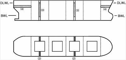
Cargo hold hatch covers and coamings | See Fig 12 |
(NOTES) 1. 2. X mark : means the point to be measured. | |
Guidance Relating to the Rules for the Classification of Steel Ships 2015 131
![]()

Pt 1 Classification and Surveys
Annex 1-5 Thickness Measurement Method for Hull Structural Member Pt 1, Annex 1-5
![]()
Table 3-1 Location and number of thickness measuring points - Non-CSR Ships (continued)
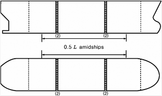
Fig 1 Locations of measurements of oil tankers and chemical tankers
132 Guidance Relating to the Rules for the Classification of Steel Ships 2015

Pt 1 Classification and Surveys
Annex 1-5 Thickness Measurement Method for Hull Structural Member Pt 1, Annex 1-5
![]()
Table 3-1 Location and number of thickness measuring points - Non-CSR Ships (continued)
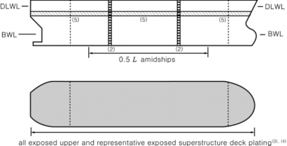
Fig 2 Locations of measurements of double hull oil tankers
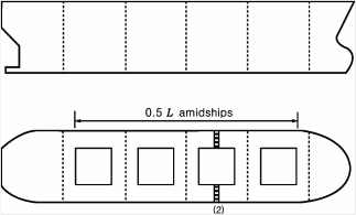
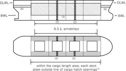
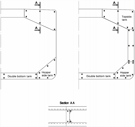
Fig 3 Locations of measurements on transverse section of single skin or double skin bulk carriers
Guidance Relating to the Rules for the Classification of Steel Ships 2015 133
Pt 1 Classification and Surveys
Annex 1-5 Thickness Measurement Method for Hull Structural Member Pt 1, Annex 1-5
![]()
Table 3-1 Location and number of thickness measuring points - Non-CSR Ships (continued)
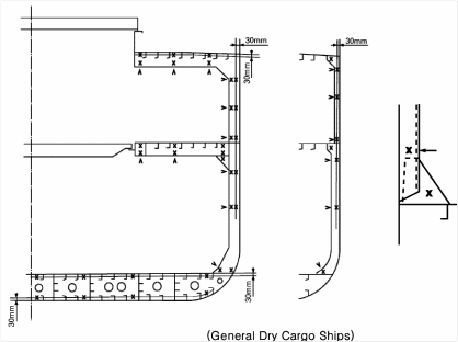
Fig 4 Locations of measurements on transverse section of general dry cargo ships
(Notes) It may also apply to other type of transverse section.
Fig 5 Locations of measurements on transverse section of general ships
134 Guidance Relating to the Rules for the Classification of Steel Ships 2015

Pt 1 Classification and Surveys
Annex 1-5 Thickness Measurement Method for Hull Structural Member Pt 1, Annex 1-5
![]()
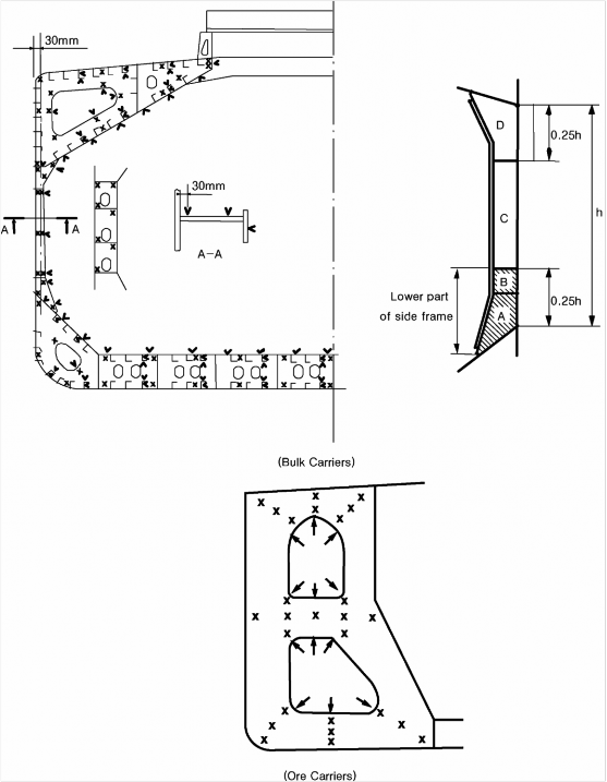
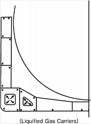
Table 3-1 Location and number of thickness measuring points - Non-CSR Ships (continued)
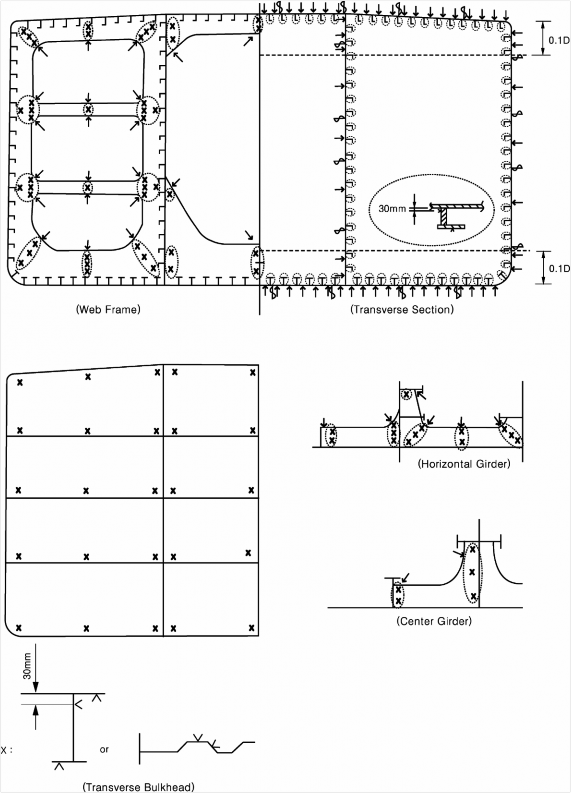
(Notes) The gauging pattern for web plating is to be a three point pattern for zones A, C and D, and a two point
pattern for zone B. The gauging report is to reflect the average reading. The average reading | is | to | be |
compared with the allowable thickness. If the web plating has general corrosion the this pattern | is | to | be |
expanded to a five point pattern. |
Fig 6 Locations of measurements on structural members in cargo holds and ballast tanks of single skin or double skin bulk carriers
Guidance Relating to the Rules for the Classification of Steel Ships 2015 135

Pt 1 Classification and Surveys
Annex 1-5 Thickness Measurement Method for Hull Structural Member Pt 1, Annex 1-5
![]()
Table 3-1 Location and number of thickness measuring points - Non-CSR Ships (continued)
(Notes) It may also apply to other ship types.
Fig 7 Locations of measurements on selected internal structural members
Fig 8 Locations of measurements on transverse frame in double skin tank of double skin bulk carriers
136 Guidance Relating to the Rules for the Classification of Steel Ships 2015
Pt 1 Classification and Surveys
Annex 1-5 Thickness Measurement Method for Hull Structural Member Pt 1, Annex 1-5
![]()
Table 3-1 Location and number of thickness measuring points - Non-CSR Ships (continued)
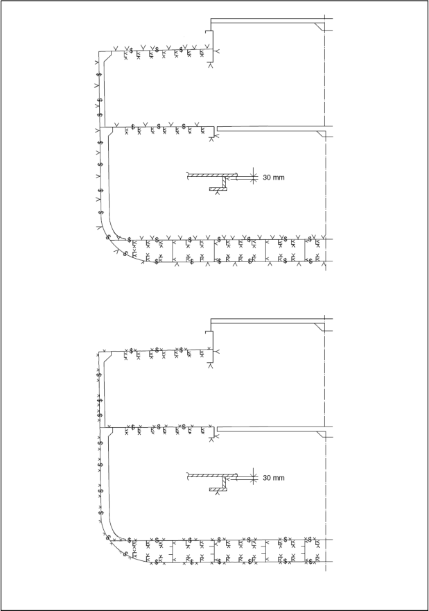
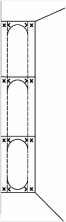
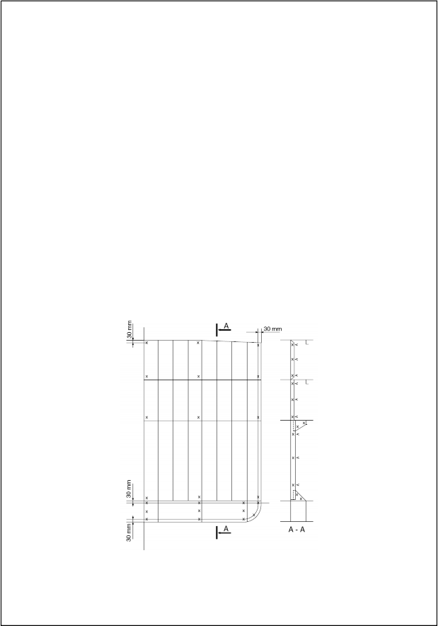
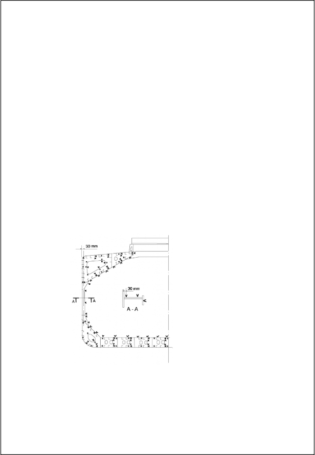
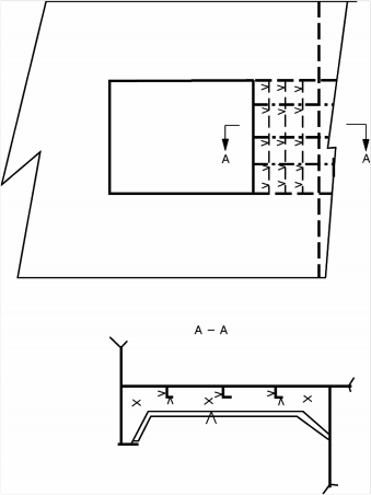
Fig 9 Locations of measurements on cargo hold transverse bulkheads of single skin or double skin bulk carriers
(Notes)
1. Cargo hold bulkhead/watertight floor plating to be measured as per main view.
2. One stiffener out of three to be measured as per view A-A.
3. It may also apply to other ship types.
Fig 10 Locations of measurements on transverse bulkheads of general dry cargo ships
Guidance Relating to the Rules for the Classification of Steel Ships 2015 137

Pt 1 Classification and Surveys
Annex 1-5 Thickness Measurement Method for Hull Structural Member Pt 1, Annex 1-5
![]()
Table 3-1 Location and number of thickness measuring points - Non-CSR Ships (continued)
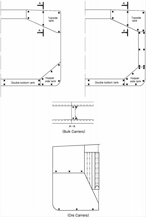
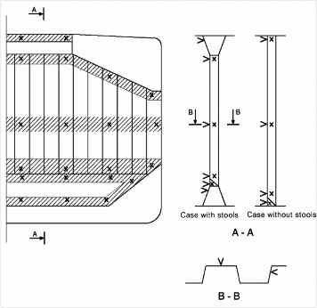
(Notes) Measurements to be taken in each vertical section as per view A-A.
Fig 11 Locations of measurements on transverse bulkheads in topside, hopper, double hull and double bottom ballast tanks of single skin or double skin bulk carriers
138 Guidance Relating to the Rules for the Classification of Steel Ships 2015

Pt 1 Classification and Surveys
Annex 1-5 Thickness Measurement Method for Hull Structural Member Pt 1, Annex 1-5
![]()
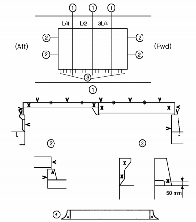
Table 3-1 Location and number of thickness measuring points - Non-CSR Ships (continued)
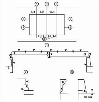
(Notes)
➀ For each hatch covers, three sections at L/4, L/2 and 3L/4 of hatch cover length, including:
- one measurement of each hatch cover plate and skirt plate
- measurements of adjacent beams or girder(including stiffeners)
- one measurement of coaming plates and coaming flange, each side
➁ For each hatch covers, one measurement of hatch cover skirt plate, coaming plate and coaming flange on both ends
➂ One measurement of one out of three hatch coaming brackets and bars, on both sides and both ends
➃ One measurement of each hatch coaming end bracket
Fig 12 Locations of measurements on hatch covers and coamings
Guidance Relating to the Rules for the Classification of Steel Ships 2015 139
Pt 1 Classification and Surveys
Annex 1-5 Thickness Measurement Method for Hull Structural Member Pt 1, Annex 1-5
![]()
Table 3-2 Location and number of thickness measuring points - CSR Ships
Table 3-2 is to be applied to vessels built under IACS Common Structural Rules(Pt 11, Pt 12 or Pt 13)
(i.e. CSR Ships).
1) CSR bulk carriers
Items | location and number of thickness measuring points | Figure reference |
Selected plates on deck, tank top, bottom, double bottom and wind-and-water area | "Selected" means at least a single point on one out of three plates, to be chosen on representative areas of average corro- sion | |
All deck, tank top and bot- tom plates and wind-and-water strakes | At least two points on each plate to be taken either at each 1/4 extremity of plate or at representative areas of average corrosion | |
Transverse section | - For single skin bulk carriers : A transverse section includes all longitudinal members such as plating, longitudinals and girders at the deck, side, bottom, inner bottom and hopper side plating, longitudinal bulkhead and bottom plating in top wing tanks. - For double skin bulk carriers : A transverse section includes all longitudinal members such as plating, longitudinals and girders at the deck, side, bottom, inner bottom and hopper sides, inner sides and top wing inner sides. | Fig 1 |
All cargo hold hatch cov- ers and coamings | Including plates and stiffeners | Locations of points are given in Fig 2 |
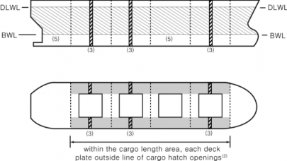
Transverse section of deck plating outside line of car- go hatch openings | Two single points on each deck plate (to be taken either at each 1/4 extremity of plate or at representative areas of aver- age corrosion) between the ship sides and hatch coamings in the transverse section concerned | |
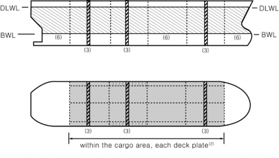
All deck plating and under deck structure inside line of hatch openings between cargo hold hatches | "All deck plating" means at least two points on each plate to be taken either at each 1/4 extremity of plate or at repre- sentative areas of average corrosion. "Underdeck structure": at each short longitudinal girder: three points for web plating(fwd/middle/aft), single point for face plate, one point for web plating and one point for face plat- ing of transverse beam in way. At each ends of transverse beams, one point for web plating and one point for face plat- ing | Extent of areas is shown in Annex 1-6, 1 (2) or (6) of the Guidance Location of points are given in Fig 6 |
140 Guidance Relating to the Rules for the Classification of Steel Ships 2015
![]()
Pt 1 Classification and Surveys
Annex 1-5 Thickness Measurement Method for Hull Structural Member Pt 1, Annex 1-5
![]()
Table 3-2 Location and number of thickness measuring points - CSR Ships (continued)
Items | location and number of thickness measuring points | Figure reference |
Single skin bulk carriers: Selected side shell frames in cargo holds for single skin bulk carriers | Includes side shell frame, upper and lower end attachments and adjacent shell plating. 25% of frames: one out of four frames should preferably be chosen throughout the cargo hold length on each side. 50% of frames: one out of two frames should preferably be chosen throughout the cargo hold length on each side. "Selected frames" means at least 3 frames on each side of cargo holds | Extent of areas is shown in Annex 1-6, 1 (2) or (6) of the Guidance Locations of points are given in Fig 3 |
Double skin bulk carriers: Transverse frame in dou- ble skin tank | Fig 1 | |
Transverse bulkheads in cargo holds | Includes bulkhead plating, stiffeners and girders, including in- ternal structure of upper and lower stools, where fitted. Two selected bulkheads: one is to be the bulkhead between the two foremost cargo holds and the second may be chosen in other positions | Areas of measure- ments are shown in Annex 1-6, 1 (2) or (6) of the Guidance Locations of points are given in Fig 4 |
One transverse bulkhead in each cargo hold | This means that the Close-up Survey and related thickness measurements are to be performed on one side of the bulk- head; the side is to be chosen based on the outcome of the overall survey of both sides. In the event of doubt, the Surveyor may also require (possibly partial) Close-up Survey and related thickness measurements on the other side | Areas of measure- ments are shown in Annex 1-6, 1 (2) or (6) of the Guidance Locations of points are given in Fig 4 |
Transverse bulkheads in one topside, hopper and double bottom ballast tank | Includes bulkhead and stiffening systems. The ballast tank is to be chosen based on the history of bal- lasting among those prone to have the most severe conditions | Locations of points are given in Fig 5 |
Transverse webs in ballast tanks | Includes web plating, face plates, stiffeners and associated plating and longitudinals. One of the representative tanks of each type (i.e. topside or hopper or side tank) is to be chosen in the forward part | Areas of measure- ments are shown in Annex 1-6, 1 (2) or (6) of the Guidance Locations of points are given in Fig 3 |
(NOTES) 1. 2. × mark : means the point to be measured. | ||
Guidance Relating to the Rules for the Classification of Steel Ships 2015 141
![]()

Pt 1 Classification and Surveys
Annex 1-5 Thickness Measurement Method for Hull Structural Member Pt 1, Annex 1-5
![]()
Table 3-2 Location and number of thickness measuring points - CSR Ships (continued)
Single skin bulk carriers
Double skin bulk carriers
(Notes) Measurements are to be taken on both port and starboard sides of the selected transverse section.
Fig 1 Locations of measurements on transverse section of single skin or double skin bulk carriers
142 Guidance Relating to the Rules for the Classification of Steel Ships 2015

Pt 1 Classification and Surveys
Annex 1-5 Thickness Measurement Method for Hull Structural Member Pt 1, Annex 1-5
![]()
Table 3-2 Location and number of thickness measuring points - CSR Ships (continued)
(Notes)
1. Three sections at L/4, L/2, 3L/4 of hatch cover length, including: one measurement of each hatch cover plate and skirt plate measurements of adjacent beams and stiffeners
one measurement of coaming plates and coaming flange, each side
2. Measurements of both ends of hatch cover skirt plate, coaming plate and coaming flange
3. One measurement(two points for web plate and one point for face plate) of one out of three hatch coam- ing brackets and bars, on both sides and both ends
Fig 2 Locations of measurements on hatch covers and coamings
Guidance Relating to the Rules for the Classification of Steel Ships 2015 143
Pt 1 Classification and Surveys
Annex 1-5 Thickness Measurement Method for Hull Structural Member Pt 1, Annex 1-5
![]()
Table 3-2 Location and number of thickness measuring points - CSR Ships (continued)
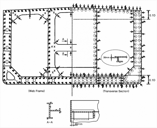
(Notes) The gauging pattern for web plating is to be a three point pattern for zones A, C and D, and a two point pattern for zone B (see figure). The gauging report is to reflect the average reading. The average reading is to be compared with the allowable thickness. If the web plating has general corrosion then this pattern is to be expanded to a five point pattern.
Single skin bulk carriers
Double skin bulk carriers
Fig 3 Locations of measurements on structural members in cargo holds and ballast tanks of single skin bulk carriers and in ballast tanks(topside or hopper or side tank) of double skin bulk carriers
144 Guidance Relating to the Rules for the Classification of Steel Ships 2015

Pt 1 Classification and Surveys
Annex 1-5 Thickness Measurement Method for Hull Structural Member Pt 1, Annex 1-5
![]()
Table 3-2 Location and number of thickness measuring points - CSR Ships (continued)
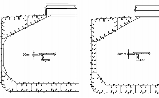
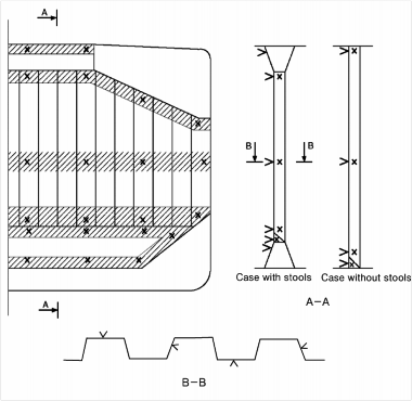
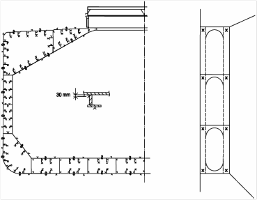
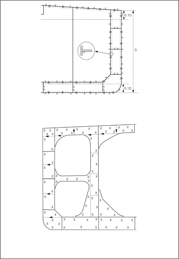
(Notes) Measurements to be taken in each shaded area as per views A-A and B-B.
Additional measurements to internal structure of upper and lower stools to be added, e.g. two points in the upper and two points in the lower stools to be indicated in section A-A.
Fig 4 Location of measurements on cargo hold transverse bulkheads of single skin or double skin bulk carriers
Guidance Relating to the Rules for the Classification of Steel Ships 2015 145

Pt 1 Classification and Surveys
Annex 1-5 Thickness Measurement Method for Hull Structural Member Pt 1, Annex 1-5
![]()
Table 3-2 Location and number of thickness measuring points - CSR Ships (continued)
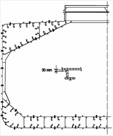
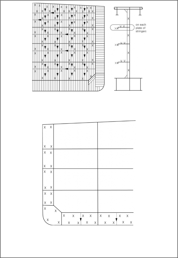
(Notes) Measurements to be taken in each vertical section as per view A-A
Two additional measurements to internal structure of double bottom tank to be added at midspan.
Fig 5 Locations of measurements on transverse bulkheads of topside, hopper, double hull and double bottom ballast tanks of single skin or double skin bulk carriers
146 Guidance Relating to the Rules for the Classification of Steel Ships 2015

Pt 1 Classification and Surveys
Annex 1-5 Thickness Measurement Method for Hull Structural Member Pt 1, Annex 1-5
![]()
Table 3-2 Location and number of thickness measuring points - CSR Ships (continued)
Fig 6 Locations of measurements on underdeck structure
Guidance Relating to the Rules for the Classification of Steel Ships 2015 147
Pt 1 Classification and Surveys
Annex 1-5 Thickness Measurement Method for Hull Structural Member Pt 1, Annex 1-5
![]()
Table 3-2 Location and number of thickness measuring points - CSR Ships (continued)
2) CSR double hull oil tankers
Items | location and number of thickness measuring points | Figure reference |
Selected plates | "Selected" means at least a single point on one out of three plates, to be chosen on representative areas of average corro- sion | |
Deck, bottom plates and wind-and-water strakes | At least two points on each plate to be taken either at each 1/4 extremity of plate or at representative areas of average corrosion | |
Transverse section | Measurements to be taken on all longitudinal members such as plating, longitudinals and girders at the deck, side, bottom, longitudinal bulkheads, inner bottom and hopper. One point to be taken on each plate. Both web and flange to be measured on longitudinals, if applicable. For tankers older than 10 years of age: within 0.1D (where D is the ship’s moulded depth) of the deck and bottom at each transverse section to be measured, every longitudinal and girder is to be measured on the web and face plate, and every plate is to be measured at one point between longitudinals. | Fig 1 |
Transverse rings3) in cargo and ballast tanks | At least two points on each plate in a staggered pattern and two points on the corresponding flange where applicable. Minimum 4 points on the first plate below deck. Additional points in way of curved parts. At least one point on each of two stiffeners between stringers / longitudinal girders. | Fig 2 |
148 Guidance Relating to the Rules for the Classification of Steel Ships 2015
![]()
Pt 1 Classification and Surveys
Annex 1-5 Thickness Measurement Method for Hull Structural Member Pt 1, Annex 1-5
![]()
![]()
Table 3-2 Location and number of thickness measuring points - CSR Ships (continued)
Items | location and number of thickness measuring points | Figure reference |
Transverse bulkheads in cargo tanks | At least two points on each plate. Minimum 4 points on the first plate below main deck. At least one point on every third stiffener to be taken be- tween each stringer. At least two points on each plate of stringers and girders, and two points on the corresponding flange. Additional points in way of curved part. Two points of each diaphragm plate of stools if fitted. | Fig 3 |
Transverse bulkheads in ballast tanks | At least 4 points on plates between stringers / longitudinal girders, or per plate if stringers / girders not fitted. At least two points on each plate of stringers and girders, and two points on the corresponding flange. Additional points in way of curved part. At least one point on two stiffeners between each stringer / longitudinal girder. | Fig 4 |
Adjacent structural mem- bers | On adjacent structural members one point per plate and one point on every third stiffener / longitudinal. | |
(NOTES) 1. mark : means the location to be measured. 2. × mark : means the point to be measured. 3. Transverse rings means all transverse material appearing in a cross-section of the ship's hull, in way of a dou- ble bottom floor, vertical web and deck transverse (definition from IACS Common Structural Rules for Double Hull Oil Tankers(Pt 12 or Pt 13 of the Rules). | ||
Guidance Relating to the Rules for the Classification of Steel Ships 2015 149
![]()
Pt 1 Classification and Surveys
Annex 1-5 Thickness Measurement Method for Hull Structural Member Pt 1, Annex 1-5
![]()
Table 3-2 Location and number of thickness measuring points - CSR Ships (continued)
Fig 1 Locations of measurements on transverse section of double hull oil tankers
Fig 2 Locations of measurements on transverse rings in cargo and ballast tanks of double hull oil tankers
150 Guidance Relating to the Rules for the Classification of Steel Ships 2015
Pt 1 Classification and Surveys
Annex 1-5 Thickness Measurement Method for Hull Structural Member Pt 1, Annex 1-5
![]()
Table 3-2 Location and number of thickness measuring points - CSR Ships (continued)
Fig 3 Locations of measurements on transverse bulkheads in cargo tanks of double hull oil tankers
Fig 4 Locations of measurements on transverse bulkheads in ballast tanks of double hull oil tankers
Guidance Relating to the Rules for the Classification of Steel Ships 2015 151
Pt 1 Classification and Surveys
Annex 1-5 Thickness Measurement Method for Hull Structural Member Pt 1, Annex 1-5
![]()
Table 4 Extent of thickness measurements at Special Survey - General Ships
No. of Special Survey | Extent and location of measurement |
Special Survey No. 1 | (1) Suspect areas throughout the vessel |
Special Survey No. 2 |
(1) Suspect areas throughout the vessel (2) One transverse section of deck plating in way of a cargo space within the amidships 0.5 |
Special Survey No. 3 |
(1) Suspect areas throughout the vessel (2) Two transverse sections within the amidships 0.5 (3) All cargo hold hatch covers and coamings(plating and stiffeners) (4) Internals in forepeak and afterpeak tanks (5) All transverse bulkheads in all cargo tanks8) (6) All transverse bulkheads in all ballast tanks8) |
152 Guidance Relating to the Rules for the Classification of Steel Ships 2015
![]()
Pt 1 Classification and Surveys
Annex 1-5 Thickness Measurement Method for Hull Structural Member Pt 1, Annex 1-5
![]()
![]()
Table 4 Extent of thickness measurements at Special Survey - General Ships (continued)
No. of Special Survey | Extent and location of measurement |
Special Survey No. 4 and Subsequent |
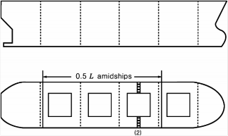
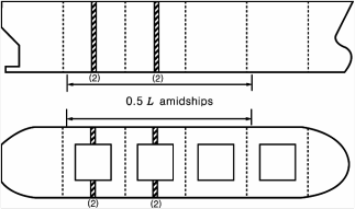
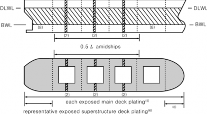
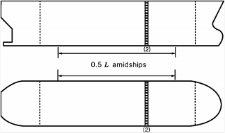
(1) Suspect areas throughout the vessel (2) A minimum of three transverse sections in way of cargo spaces within the amidships 0.5 5), 6), 7) (3) All cargo hold hatch covers and coamings(plating and stiffeners) (4) Internals in forepeak and afterpeak tanks (5) All exposed main deck plating full length (6) Representative exposed superstructure deck plating(poop, bridge and forecastle deck) (7) Lowest strake and strakes in way of 'tween decks of all transverse bulkheads in cargo spaces together with internals in way (8) All wind and water strakes, port and starboard, full length (9) All keel plates full length. Also, additional bottom plates in way of cofferdams, machi- nery space and aft end of tanks (10) Plating of seachests. Shell plating in way of overboard discharges as considered nec- essary by the attending Surveyor (11) All transverse bulkheads and one web frame ring in all cargo tanks8) (12) All transverse bulkheads and all web frame ring in all ballast tanks8) |
(NOTES) Thickness gaugings for deck plates Thickness gaugings for side shell plates Thickness gaugings for the transverse section(applied for plates only) Thickness gaugings for the transverse section(including longitudinal members, for trans- versely framed vessels including adjacent frames and their end connections in way of transverse sections) 1) In application to this table, General Ships means ships except Other Ships in Table 1.2.4, 2. of the Rules. 2) Thickness measurement locations are to be selected to provide the best representative sampling of areas likely to be most exposed to corrosion, considering cargo and ballast history and arrangement and con- dition of protective coatings. 3) Thickness measurements of internals may be specially considered by the Surveyor if the hard protective coating is in GOOD condition. 4) For ships more than 100 meters in length, at Special Survey No. 3, thickness measurements of exposed deck plating within amidship 0.5 may be required. 5) For ships less than 100 meters in length, the number of transverse sections required at Special Survey No. 3 may be reduced to one (1), and the number of transverse sections required at Special Survey No. 4 and subsequent may be reduced to two (2). 6) For the pure car carrier, the extent of thickness measurement for transverse sections may by considered as follow: Exposed deck plates, side shell plates, bottom shell plates, inner bottom plates and longitudinal members in double bottom spaces. 7) Where the evaluation of longitudinal strength is required, all longitudinal structural members at the corre- sponding sections are to be gauged. 8) This requirement is to be applied only for tankers(including barges) for liquid cargo. | |
![]()
![]()
Guidance Relating to the Rules for the Classification of Steel Ships 2015 153
![]()
Pt 1 Classification and Surveys
Annex 1-5 Thickness Measurement Method for Hull Structural Member Pt 1, Annex 1-5
![]()
Table 5 Extent of thickness measurements at Special Survey - Other Ships
No. of Special Survey | Extent and location of measurement |
Special Survey No. 1 | (1) Suspect areas throughout the vessel |
Special Survey No. 2 |
(1) Suspect areas throughout the vessel (2) One transverse section of deck plating5), side shell plating and bottom plating within the amidships 0.5 |
Special Survey No. 3 |
(1) Suspect areas throughout the vessel (2) Two transverse sections of deck plating5), side shell plating and bottom plating within the amidships 0.5 (3) Internals in forepeak and afterpeak tanks |
154 Guidance Relating to the Rules for the Classification of Steel Ships 2015
![]()
Pt 1 Classification and Surveys
Annex 1-5 Thickness Measurement Method for Hull Structural Member Pt 1, Annex 1-5
![]()

Table 5 Extent of thickness measurements at Special Survey - Other Ships (continued)
No. of Special Survey | Extent and location of measurement |
Special Survey No. 4 and Subsequent |
(1) Suspect areas throughout the vessel (2) Two transverse sections of side shell plating within the amidships 0.5 (3) Full length, all exposed main deck plating5) (4) Full length, representative exposed superstructure deck plating(poop, bridge and forecastle deck) (5) Full length, selected wind and water strakes (6) Full length, bottom plating and flat keel plating (7) Internals in forepeak and afterpeak tanks |
(NOTES) Thickness gaugings for deck plates Thickness gaugings for side shell plates Thickness gaugings for the transverse section(applied for plates only) 1) In application to this table, Other Ships means the ship specified as follows except Special Purpose Ship - Waste in Annex 1-1, 1.1 of the Guidance. - the ship type 12, 13 - the ship less than 500 GT and not engaged on international voyages among ship type 15, 16, 17, 19, 20 and 26 to 30. 2) Thickness measurement locations are to be selected to provide the best representative sampling of area likely to be most exposed to corrosion. 3) Thickness measurements of internals may be specially considered by the Surveyor if the hard protective coating is in GOOD condition. 4) When the evaluation of longitudinal strength is required, all longitudinal structural members at the corre- sponding sections are to be gauged. 5) For fishing vessel, thickness measurement requirements in way of deck(gutter water way part and hatch coaming part) may be modified at the discretion of the Surveyor if the structure remains effectively pro- tected against corrosion by a permanent type special coating. | |
Guidance Relating to the Rules for the Classification of Steel Ships 2015 155
![]()
Pt 1 Classification and Surveys
Annex 1-5 Thickness Measurement Method for Hull Structural Member Pt 1, Annex 1-5
![]()
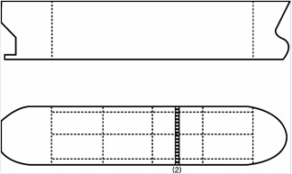
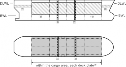
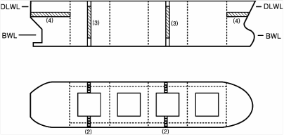
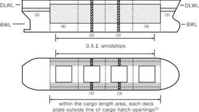
Table 6 Extent of thickness measurements at Special Survey - General Dry Cargo Ships
No. of Special Survey | Extent and location of measurement |
Special Survey No. 1 | (1) Suspect areas |
Special Survey No. 2 |
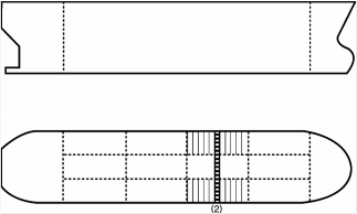
(1) Suspect areas (2) One transverse section of deck plating in way of a cargo length area within the amidships 0.5 (3) Measurement for general assessment and recording of corrosion pattern of those structural members subject to Close-up Survey |
Special Survey No. 3 |
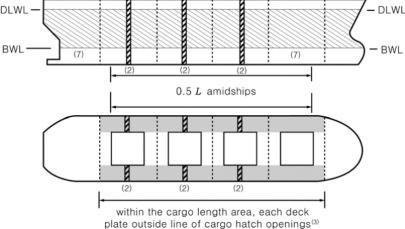
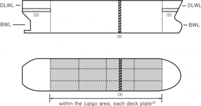
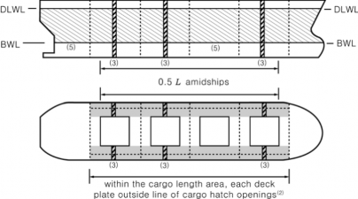
(1) Suspect areas (2) Two transverse sections within the amidships 0.5 (3) Measurement for general assessment and recording of corrosion pattern of those structural members subject to Close-up Survey (4) Within the cargo length area, each deck plate outside line of cargo hatch openings (5) All wind and water strakes within the cargo length area (6) Selected wind and water strakes outside the cargo length area |
156 Guidance Relating to the Rules for the Classification of Steel Ships 2015
![]()
Pt 1 Classification and Surveys
Annex 1-5 Thickness Measurement Method for Hull Structural Member Pt 1, Annex 1-5
![]()
![]()
Table 6 Extent of thickness measurements at Special Survey - General Dry Cargo Ships (continued)
No. of Special Survey | Extent and location of measurement |
Special Survey No. 4 and Subsequent |
(1) Suspect areas (2) Within the cargo length area, a minimum of three transverse sections within the amidships 0.5 2) (3) Within the cargo length area, each deck plate outside line of cargo hatch openings (4) Within the cargo length area, each bottom plate, including lower turn of bilge (5) Within the cargo length area, duct keel or pipe tunnel plating and internals (6) Measurement for general assessment and recording of corrosion pattern of those structural members subject to Close-up Survey (7) All wind and water strakes full length |
(NOTES) Thickness gaugings for deck plates Thickness gaugings for side shell plates Thickness gaugings for the transverse section(applied for plates only) Thickness gaugings for the transverse section(including longitudinal members, for transversely framed vessels including adjacent frames and their end connections in way of transverse sections) 1) Thickness measurement locations are to be selected to provide the best representative sampling of area likely to be most exposed to corrosion, considering cargo and ballast history and arrangement and con- dition of protective coatings. 2) For ships less than 100 meters in length, the number of transverse sections required at Special Survey No. 3 may be reduced to one and the number of transverse sections at Special Survey No. 4 and sub- sequent surveys may be reduced to two. | |
![]()
Guidance Relating to the Rules for the Classification of Steel Ships 2015 157
![]()
Pt 1 Classification and Surveys
Annex 1-5 Thickness Measurement Method for Hull Structural Member Pt 1, Annex 1-5
![]()
Table 7 Extent of thickness measurements at Special Survey - Liquefied Gas Carriers
No. of Special Survey | Extent and location of measurement |
Special Survey No. 1 |
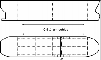
(1) Suspect areas (2) One section of deck plating for the full beam of the ship within 0.5 (3) Measurement for general assessment and recording of corrosion pattern of those structural members subject to Close-up Survey |
Special Survey No. 2 |
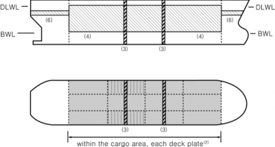
(1) Suspect areas (2) Within the cargo area, each deck plate (3) Within the cargo area, one transverse section within 0.5 (4) Selected wind and water strakes outside the cargo area (5) Measurement for general assessment and recording of corrosion pattern of those structural members subject to Close-up Survey |
158 Guidance Relating to the Rules for the Classification of Steel Ships 2015
![]()
Pt 1 Classification and Surveys
Annex 1-5 Thickness Measurement Method for Hull Structural Member Pt 1, Annex 1-5
![]()
Table 7 Extent of thickness measurements at Special Survey - Liquefied Gas Carriers (continued)
No. of Special Survey | Extent and location of measurement |
Special Survey No. 3 |
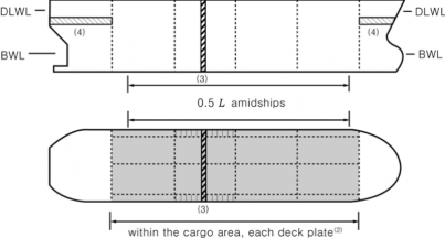
(1) Suspect areas (2) Within the cargo area, each deck plate (3) Within the cargo area, two transverse sections1) (4) Within the cargo area, all wind and water strakes (5) Selected wind and water strakes outside the cargo area (6) Measurement for general assessment and recording of corrosion pattern of those structural members subject to Close-up Survey |
Special Survey No. 4 and Subsequent |
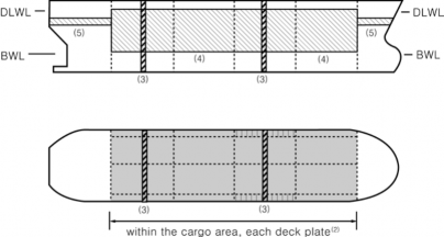
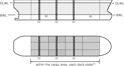
(1) Suspect areas (2) Within the cargo area, each deck plate (3) Within the cargo area, three transverse sections1) (4) Within the cargo area, each bottom plate (5) Within the cargo area, duct keel plating and internals (6) All wind and water strakes, full length (7) Measurement for general assessment and recording of corrosion pattern of those structural members subject to Close-up Survey |
Guidance Relating to the Rules for the Classification of Steel Ships 2015 159
![]()
Pt 1 Classification and Surveys
Annex 1-5 Thickness Measurement Method for Hull Structural Member Pt 1, Annex 1-5
![]()
![]()

Table 7 Extent of thickness measurements at Special Survey - Liquefied Gas Carriers (continued)
(NOTES)
Thickness gaugings for deck plates Thickness gaugings for side shell plates
Thickness gaugings for the transverse section(applied for plates only)
Thickness gaugings for the transverse section(including longitudinal members, for transversely framed vessels including adjacent frames and their end connections in way of transverse sec- tions)
1) At least one section is to include a ballast tank within 0.5 amidships, if any.
2) For ships having independent tanks of type C, with a midship section similar to that of a general cargo ship, the extent of thickness measurements may be increased to include the tank top plating at the discretion of the Surveyor.
3) For areas in spaces where protective coatings are found to be in GOOD condition, the extent of thickness measurements may be specially considered by the Society.
4) The Surveyor may extend the thickness measurements as deemed necessary. Where substantial corrosion is found, the extent of thickness measurements is to be increased to the satisfaction of the Surveyor.
160 Guidance Relating to the Rules for the Classification of Steel Ships 2015
![]()
Pt 1 Classification and Surveys
Annex 1-5 Thickness Measurement Method for Hull Structural Member Pt 1, Annex 1-5
![]()
Table 8 Extent of thickness measurements at Special Survey - Bulk Carriers with ESP notation
No. of
Special Survey Extent and location of measurement
Special Survey
No. 1 (1) Suspect areas
Special Survey No. 2
(1) Suspect areas
(2) Within the cargo length, two transverse sections of deck plating outside line of cargo hatch openings
(3) Wind and water strakes in way of transverse sections considered under (2) above
(4) Selected wind and water strakes outside the cargo length area
(5) Measurement for, general assessment and recording of corrosion pattern, of those structural members subject to Close-up Survey
(6) See Ch 3, 201. 1 (4) of the Rules, Pt 7, Ch 3, Sec 17 of the Rules and the separate re- quirements specified by the Society for additional thickness measurement guidelines applicable to the side shell frames and brackets on ships subject to compliance with IACS UR S31
Special Survey 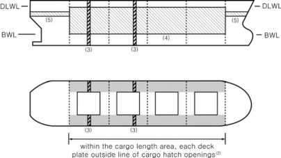
No. 3 (1) Suspect areas
(2) Within the cargo length, each deck plate outside line of cargo hatch openings
(3) Within the cargo length, two transverse sections, one in the amidship area, outside line of cargo hatch openings
(4) Within the cargo length, all wind and water strakes
(5) Selected wind and water strakes outside the cargo length area
(6) Measurement for, general assessment and recording of corrosion pattern, of those structural members subject to Close-up Survey
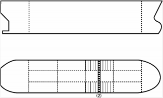
(7) See Ch 3, 201. 1 (3) of the Rules and Annex 1-5, Table 9 of the Guidance for additional thickness measurement guidelines applicable to the vertically corrugated transverse watertight bulkhead between cargo hold Nos. 1 and 2 on ships subject to compliance with IACS URs S19 and S23
(8) See Ch 3, 201. 1 (4) of the Rules, Pt 7, Ch 3, Sec 17 of the Rules and the separate re- quirements specified by the Society for additional thickness measurement guidelines applicable to the side shell frames and brackets on ships subject to compliance with IACS UR S31
Guidance Relating to the Rules for the Classification of Steel Ships 2015 161
![]()
Pt 1 Classification and Surveys
Annex 1-5 Thickness Measurement Method for Hull Structural Member Pt 1, Annex 1-5
![]()
Table 8 Extent of thickness (continued)
measurements at Special Survey - Bulk Carriers with ESP notation
No. of Special Survey | Structural members to be measured |
Special Survey No. 4 and Subsequent |
(1) Suspect areas (2) Within the cargo length, each deck plate outside line of cargo hatch openings (3) Within the cargo length, three transverse sections, one in the amid ship area, outside line of cargo hatch openings (4) Within the cargo length, each bottom plates (5) All wind and water strakes, full length (6) Measurement for, general assessment and recording of corrosion pattern, of those structural members subject to Close-up Survey (7) See Ch 3, 201. 1 (3) of the Rules and Annex 1-5, Table 9 of the Guidance for addi- tional thickness measurement guidelines applicable to the vertically corrugated transverse wa- tertight bulkhead between cargo hold Nos. 1 and 2 on ships subject to compliance with IACS URs S19 and S23 (8) See Ch 3, 201. 1 (4) of the Rules, Pt 7, Ch 3, Sec 17 of the Rules and the separate re- quirements specified by the Society for additional thickness measurement guidelines appli- cable to the side shell frames and brackets on ships subject to compliance with IACS UR S31 |
(NOTES) Thickness gaugings for deck plates Thickness gaugings for side shell plates Thickness gaugings for the transverse section(applied for plates only) Thickness gaugings for the transverse section(including longitudinal members, for transversely framed vessels including adjacent frames and their end connections in way of transverse sections) | |
![]()
162 Guidance Relating to the Rules for the Classification of Steel Ships 2015
![]()
Pt 1 Classification and Surveys
Annex 1-5 Thickness Measurement Method for Hull Structural Member Pt 1, Annex 1-5
![]()
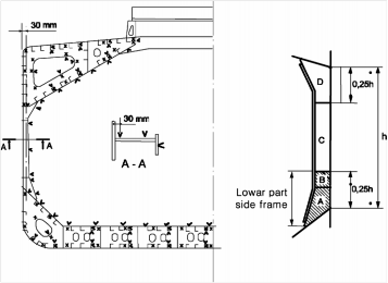
Table 9 Additional thickness measurements head between holds Nos. 1 and 2
of the vertically corrugated transverse watertight bulk-
Location | Vertically corrugated transverse watertight bulkhead between holds Nos. 1 and 2 |
Gauging point | 1. The gauging is to be carried out at the levels as described below. To adequately assess the scantlings of each individual vertical corrugation, each corrugation flange, webs, shedder plate and gusset plate within each of the levels given below are to be gauged. (1) Level (A) : Ships without lower stool (See Fig 1) (a) The mid-breadth of the corrugation flanges at approximately 200 mm above the line of shedder plates; (b) The middle of gusset plates between corrugation flanges, where fitted; (c) The middle of the shedder plates; (d) The mid-breadth of the corrugation webs at approximately 200 mm above the line of shedder plates. (2) Level (B) : Ships with lower stool (See Fig 2) (a) The mid-breadth of the corrugation flanges at approximately 200 mm above the line of shedder plates; (b) The middle of gusset plates between corrugation flanges, where fitted; (c) The middle of the shedder plates; (d) The mid-breadth of the corrugation webs at approximately 200 mm above the line of shedder plates. (3) Level (C) : Ships with or without lower stool (See Fig 1 or Fig 2) (a) The mid-breadth of the corrugation flanges and webs at about the mid-height of the corrugation. 2. Where the thickness changes within the horizontal levels, the thinner plate is to be gauged. |
| |
Guidance Relating to the Rules for the Classification of Steel Ships 2015 163
![]()
Pt 1 Classification and Surveys
Annex 1-5 Thickness Measurement Method for Hull Structural Member Pt 1, Annex 1-5
![]()
Table 10 Extent of thickness measurements at Special Survey - Oil Tankers with ESP notation
No. of Special Survey | Extent and location of measurement |
Special Survey No. 1 |
(1) Suspect areas (2) One transverse section of deck plates for the full beam of the ship within the cargo area (in way of a ballast tank, if any, or a cargo tank used primarily for water ballast) (3) Measurements, for general assessment and recording of corrosion pattern, of those structural members subject to Close-up Survey |
Special Survey No. 2 |
(1) Suspect areas (2) Within the cargo area, each deck plate (3) Within the cargo area, one transverse section (4) Measurements, for general assessment and recording of corrosion pattern, of those structural members subject to Close-up Survey (5) Selected wind and water strakes outside the cargo area |
164 Guidance Relating to the Rules for the Classification of Steel Ships 2015
![]()
Pt 1 Classification and Surveys
Annex 1-5 Thickness Measurement Method for Hull Structural Member Pt 1, Annex 1-5
![]()
Table 10 Extent of
(continued)
thickness measurements at Special Survey - Oil Tankers with ESP notation
No. of Special Survey | Extent and location of measurement |
Special Survey No. 3 |
(1) Suspect area (2) Within the cargo area, each deck plate (3) Within the cargo area, two transverse sections1) (4) Within the cargo area, all wind and water strakes (5) Measurements, for general assessment and recording of corrosion pattern, of those structural members subject to Close-up Survey (6) Selected wind and water strakes outside the cargo area |
Special Survey No. 4 and Subsequent |
(1) Suspect areas (2) Within the cargo area, each deck plate (3) Within the cargo area, three transverse sections1) (4) Within the cargo area, each bottom plate (5) Measurements, for general assessment and recording of corrosion pattern, of those structural members subject to Close-up Survey (6) All wind and water strakes, full length |
(NOTES) Thickness gaugings for deck plates Thickness gaugings for side shell plates Thickness gaugings for the transverse section(applied for plates only) Thickness gaugings for the transverse section(including longitudinal members, for transversely framed vessels including adjacent frames and their end connections in way of transverse sections) Thickness gaugings in way of the ballast tank 1) At least one section is to include a ballast tank within 0.5 | |
![]()
Guidance Relating to the Rules for the Classification of Steel Ships 2015 165
![]()
Pt 1 Classification and Surveys
Annex 1-5 Thickness Measurement Method for Hull Structural Member Pt 1, Annex 1-5
![]()
Table 11 Extent of thickness measurements at Special Survey - Chemical Tankers with ESP notation
No. of Special Survey | Extent and location of measurement |
Special Survey No. 1 |
(1) Suspect areas (2) One transverse section of deck plating for the full beam of the ship within the cargo area (in way of a ballast tank, if any, or a cargo tank used primarily for water ballast) (3) Measurements, for general assessment and recording of corrosion pattern, of those structural members subject to Close-up Survey |
Special Survey No. 2 |
(1) Suspect areas (2) Within the cargo area, each deck plate (3) Within the cargo area, one transverse section (4) Measurements, for general assessment and recording of corrosion pattern, of those structural members subject to Close-up Survey (5) Selected wind and water strakes outside the cargo area |
166 Guidance Relating to the Rules for the Classification of Steel Ships 2015
![]()
Pt 1 Classification and Surveys
Annex 1-5 Thickness Measurement Method for Hull Structural Member Pt 1, Annex 1-5
![]()
Table 11 Extent of thickness measurements at Special Survey - Chemical Tankers with ESP notation (continued)
No. of Special Survey | Extent and location of measurement |
Special Survey No. 3 |
(1) Suspect area (2) Within the cargo area, each deck plate (3) Within the cargo area, two transverse sections1) (4) Within the cargo area, all wind and water strakes (5) Measurements, for general assessment and recording of corrosion pattern, of those struc- tural members subject to Close-up Survey (6) Selected wind and water strakes outside the cargo area |
Special Survey No. 4 and Subsequent |
(1) Suspect areas (2) Within the cargo area, each deck plate (3) Within the cargo area, three transverse sections1) (4) Within the cargo area, each bottom plate (5) Measurements, for general assessment and recording of corrosion pattern, of those struc- tural members subject to Close-up Survey (6) All wind and water strakes, full length |
(NOTES) Thickness gaugings for deck plates Thickness gaugings for side shell plates Thickness gaugings for the transverse section(applied for plates only) Thickness gaugings for the transverse section(including longitudinal members, for transversely framed vessels including adjacent frames and their end connections in way of transverse sections) Thickness gaugings in way of the ballast tank 1) At least one section is to include a ballast tank within 0.5 | |
![]()
Guidance Relating to the Rules for the Classification of Steel Ships 2015 167
![]()
Pt 1 Classification and Surveys
Annex 1-5 Thickness Measurement Method for Hull Structural Member Pt 1, Annex 1-5
![]()
Table 12 Extent of thickness measurements at Special Survey - Double Hull Oil Tankers with ESP notation
No. of Special Survey | Extent and location of measurement |
Special Survey No. 1 |
(1) Suspect areas (2) One section of deck plating for the full beam of the ship within the cargo area (3) Measurements, for general assessment and recording of corrosion pattern, of those structural members subject to Close-up Survey |
Special Survey No. 2 |
(1) Suspect areas (2) Within the cargo area, each deck plate (3) Within the cargo area, one transverse section (4) Measurements, for general assessment and recording of corrosion pattern, of those structural members subject to Close-up Survey (5) Selected wind and water strakes outside the cargo area |
168 Guidance Relating to the Rules for the Classification of Steel Ships 2015
![]()
Pt 1 Classification and Surveys
Annex 1-5 Thickness Measurement Method for Hull Structural Member Pt 1, Annex 1-5
![]()
Table 12 Extent of thickness measurements at Special Survey - Double Hull Oil Tankers with ESP notation (continued)
No. of Special Survey | Extent and location of measurement |
Special Survey No. 3 |
(1) Suspect areas (2) Within the cargo area, each deck plate (3) Within the cargo area, two transverse sections1) (4) Within the cargo area, all wind and water strakes (5) Measurements, for general assessment and recording of corrosion pattern, of those structural members subject to Close-up Survey (6) Selected wind and water strakes outside the cargo area |
Special Survey No. 4 |
(1) Suspect areas (2) Within the cargo area, each deck plate (3) Within the cargo area, three transverse sections1) (4) Within the cargo area, each bottom plate (5) Measurements, for general assessment and recording of corrosion pattern, of those structural members subject to Close-up Survey (6) All wind and water strakes, full length |
(NOTES) Thickness gaugings for deck plates Thickness gaugings for side shell plates Thickness gaugings for the transverse section(applied for plates only) Thickness gaugings for the transverse section(including longitudinal members, for transversely framed vessels including adjacent frames and their end connections in way of transverse sections) Thickness gaugings in way of the ballast tank 1) At least one section is to include a ballast tank within 0.5 | |
![]()
Guidance Relating to the Rules for the Classification of Steel Ships 2015 169
![]()
Pt 1 Classification and Surveys
Annex 1-5 Thickness Measurement Method for Hull Structural Member Pt 1, Annex 1-5
![]()
Table 13 Extent of thickness measurements at Special Survey - Double Skin Bulk Carriers with ESP notation
No. of Special Survey | Extent and location of measurement |
Special Survey No. 1 | (1) Suspect areas |
Special Survey No. 2 |
(1) Suspect areas (2) Within the cargo length, two transverse sections of deck plating outside line of car- go hatch openings (3) Wind and water strakes in way of the two transverse sections considered (2) above (4) Selected wind and water strakes outside the cargo length area (5) Measurements, for general assessment and recording of corrosion pattern, of those structural members subject to Close-up Survey |
Special Survey No. 3 |
(1) Suspect areas (2) Within the cargo length, each deck plate outside line of cargo hatch openings (3) Within the cargo length, two transverse sections, one in the amidship area, outside line of cargo hatch openings (4) Within the cargo length, all wind and water strakes (5) Selected wind and water strakes outside the cargo length area (6) Measurements, for general assessment and recording of corrosion pattern, of those structural members subject to Close-up Survey |
170 Guidance Relating to the Rules for the Classification of Steel Ships 2015
![]()
Pt 1 Classification and Surveys
Annex 1-5 Thickness Measurement Method for Hull Structural Member Pt 1, Annex 1-5
![]()
Table 13 Extent of thickness measurements at Special Survey - Double Skin Bulk Carriers with ESP notation (continued)
No. of Special Survey | Extent and location of measurement |
Special Survey No. 4 |
(1) Suspect areas (2) Within the cargo length, each deck plate outside line of cargo hatch openings (3) Within the cargo length, three transverse sections, one in the amidship area, outside line of cargo hatch openings (4) Within the cargo length, each bottom plate (5) All wind and water strakes, full length (6) Measurements, for general assessment and recording of corrosion pattern, of those structural members subject to Close-up Survey |
(NOTES) Thickness gaugings for deck plates Thickness gaugings for side shell plates Thickness gaugings for the transverse section(applied for plates only) Thickness gaugings for the transverse section(including longitudinal members, for transversely framed vessels including adjacent frames and their end connections in way of transverse sections) | |
![]()
Guidance Relating to the Rules for the Classification of Steel Ships 2015 171
![]()
Pt 1 Classification and Surveys
Annex 1-5 Thickness Measurement Method for Hull Structural Member Pt 1, Annex 1-5
![]()
Table 14 Requirements for extent of thickness measurements at those areas of substantial corrosion
- Bulk Carriers with ESP notation
1) Shell Structures
Structural Member | Extent of Measurement | Pattern of measurement |
1. Bottom and Side Shell Plating | 1) Suspect plate, plus four adjacent plates 2) See other tables for particulars on gauging in way tanks and cargo holds | 1) 5 point pattern for each panel between longitudinals |
2. Bottom/Side Shell Longitudinals | Minimum of three longitudinals in way of suspect areas | 3 measurement in line across web 3 measurement on flange |
2) Transverse Bulkheads in Cargo Holds
Structural member | Extent of Measurement | Pattern of measurement |
1. Lower Stool | 1) Transverse band within 25 mm of welded connection to inner-bottom 2) Transverse band within 25 mm of welded connection to shelf plate | 1) 5 point between stiffeners over 1 metre length 2) 5 point between stiffeners over 1 metre length |
2. Transverse Bulkhead | 1) Transverse band at approximately mid height 2) Transverse band at part of bulkhead adjacent to upper deck or below upper stool shelf plate (for those ships fitted with upper stools) | 1) 5 point pattern over 1 sq. metre of plating 2) 5 point pattern over 1 sq. metre of plating |
3) Deck Structure including Cross Strips, Main Cargo Hatchways, Hatch Covers, Coamings and Topside Tanks
Structural Member | Extent of Measurement | Pattern of Measurement |
1. Cross Deck Strip Plating | Suspect cross deck strip plating | 5 point pattern between underdeck stiffeners over 1 metre length |
2. Underdeck Stiffeners | 1) Transverse members 2) Longitudinal member | 1) 5 point pattern at each end and mid span 2) 5 point pattern on both web and flange |
3. Hatch Covers | 1) Side and end skirts, each 3 locations 2) 3 longitudinal bands, outboard strakes (2) and centerline strake (1) | 1) 5 point pattern at each location 2) 5 point measurement each band |
4. Hatch Coamings | Each side and end of coaming, one band lower 1/3, one band upper 2/3 of coam- ing | 5 point measurement each band i.e. end or side coaming |
5. Topside Ballast Tanks | 1) Watertight transverse bulkheads a) lower 1/3 of bulkhead b) upper 2/3 of bulkhead c) stiffeners 2) 2 representative swash transverse bulk- heads a) lower 1/3 of bulkhead b) upper 2/3 of bulkhead c) stiffeners 3) 3 representative bays of slop plating a) lower 1/3 of tank b) upper 2/3 of tank 4) Longitudinals, suspect and adjacent | 1) a) 5 point pattern over 1 sq. metre of plating b) 5 point pattern over 1 sq. metre of plating c) 5 point pattern over 1 metre length 2) a) 5 point pattern over 1 sq. metre of plating b) 5 point pattern over 1 sq. metre of plating c) 5 point pattern over 1 metre length 3) a) 5 point pattern over 1 sq. metre of plating b) 5 point pattern over 1 sq. metre of plating 4) 5 point pattern both web and flange over 1 metre length |
6. Main Deck Plating | Suspect plates and adjacent (4) | 5 point pattern over 1 sq. metre of plating |
7. Main Deck Longitudinals | Minimum of 3 longitudinals where plat- ing measured | 5 point pattern on both web and flange over 1 metre length |
8. Web Frames /Transverses | Suspect plates | 5 point pattern over 1 sq. metre |
172 Guidance Relating to the Rules for the Classification of Steel Ships 2015
![]()
Pt 1 Classification and Surveys
Annex 1-5 Thickness Measurement Method for Hull Structural Member Pt 1, Annex 1-5
![]()
Table 14 Requirements for extent of thickness measurements at those areas of substantial corrosion
- Bulk Carriers with ESP notation (continued)
4) Double Bottom and Hopper Structure
Structural Member | Extent of Measurement | Pattern of Measurement |
1. Inner/Double Bottom Plating | Suspect plate plus all adjacent plates | 5 point pattern for each panel between longitudinals over 1 metre length |
2. Inner/Double Bottom Longitudinals | Three longitudinals where plates measured | 3 measurements in line across web and 3 measurements on flange |
3. Longitudinal Girders or Transverse Floors | Suspect plates | 5 point pattern over about 1 square metre |
4. Watertight Bulkhead (W.T Floors) | 1) lower 1/3 of tank 2) upper 2/3 of tank | 1) 5 point pattern over 1 sq. metre of plating 2) 5 point pattern alternate plates over 1 sq. metre of plating |
5. Web Frames | Suspect plating | 5 point pattern over 1 sq. metre of plating |
6. Bottom/Side Shell Longitudinals | Minimum of three longitudinals in way of suspect areas | 3 measurements in line across web 3 measurements on flange |
5) Cargo Holds
Structural Member | Extent of Measurement | Pattern of Measurement | |||
1. Side Shell Frames | Suspect adjacent | frame frame | and | each | a) At each end and mid span : 5 point pattern of both web and flange b) 5 point pattern within 25 mm of welded attachment of both shell and lower slope plate |
Guidance Relating to the Rules for the Classification of Steel Ships 2015 173
![]()
Pt 1 Classification and Surveys
Annex 1-5 Thickness Measurement Method for Hull Structural Member Pt 1, Annex 1-5
![]()
Table 15 Requirements for extent of thickness measurements at those areas of substantial corrosion
- Oil Tankers, Ore/Oil Ships, Etc. with ESP notation
1) Bottom Structure
Structural Member | Extent of Measurement | Pattern of Measurement |
1. Bottom Plating | Minimum of 3 bays across tank including aft bay Measurements around and under all bell mouths | 5 point pattern for each panel between longitudinals and webs |
2. Bottom Longitudinals | Minimum of 3 longitudinals in each bay where bottom plating measured | 3 measurements in line across flange and 3 measurements on vertically web |
3. Bottom Girders and Brackets | At fore and aft transverse bulkhead bracket toes and in centre of tanks | Vertical line of single measurements on web plating with one measurement between each panel stiffener, or a minimum of three measurements Two measurements across face flat5 point pattern on girder/bulkhead brackets |
4. Bottom Transverse Webs | 3 webs in bays where bottom plating measured, with measurements at both ends and middle | 5 points pattern over 2 square metre area Single measurements on face flat |
5. Panel Stiffening | Where provided | Single measurements |
2) Deck Structure
Structural Member | Extent of Measurement | Pattern of Measurement |
1. Deck Plating | Two bands across tank | Minimum of three measurements per plate per band |
2. Deck Longitudinals | Minimum of 3 longitudinals in each of two bands | 3 measurements in line vertically on webs, and 2 measurements on flange (if fitted) |
3. Deck Girders and Brackets | At fore and aft transverse bulk- head, bracket toes and in centre of tanks | Vertical line of single measurements on web plating with one measurement between each panel stiffener, or a minimum of three measurements Two measurements across face flat. 5 point pattern on girder/bulkhead brackets |
4. Deck Transverse Webs | Minimum of two webs with measurements at middle and both ends of span | 5 points pattern over about 2 square metre areas Single measurements on face flat |
5. Panel Stiffening | Where provided | Single measurement |
174 Guidance Relating to the Rules for the Classification of Steel Ships 2015
![]()
Pt 1 Classification and Surveys
Annex 1-5 Thickness Measurement Method for Hull Structural Member Pt 1, Annex 1-5
![]()
Table 15 Requirements for extent of thickness measurements at those areas of substantial corrosion
- Oil Tankers, Ore/Oil Ships, Etc. with ESP notation (continued)
3) Side Shell and Longitudinal Bulkheads
Structural Member | Extent of Measurement | Pattern of Measurement |
1. Deckhead and Bottom Strakes, and Strakes in way of Stringer Platforms | Plating between each pair of longitudinals in a minimum of 3 bays | Single measurement |
2. All Other Strakes | Plating between every 3rd pair of longitudinals in same 3 bays | Single measurement |
3. Longitudinals-deckhead and Bottom Strakes | Each longitudinal in same 3 bays | 3 measurements across web and 1 measurement on flange |
4. Longitudinals - All Others | Every third longitudinal in same 3 bays | 3 measurements across web and 1 measurement on flange |
5. Longitudinals - Bracket | Minimum of three at top middle and bottom of tank in same 3 bays | 5 point pattern over area of bracket |
6. Web Frames and Cross Ties | 3 webs with minimum of three loca- tions on each web, including in way of cross tie connections | 5 point pattern over about 2 square metre area, plus single measurements on web frame and cross tie face flats |
4) Transverse Bulkheads and Swash Bulkheads
Structural Member | Extent of Measurement | Pattern of Measurement |
1. Deckhead and Bottom Strakes, and Strakes in way of Stringer Platforms | Plating between pair of stiffeners at three locations - approx. 1/4, 1/2 and 3/4 width of tank | 5 points pattern between stiffeners over 1 meter length |
2. All Other Strakes | Plating between pair of stiffeners at middle location | Single measurement |
3. Strakes in Corrugated Bulkheads | Plating for each change of scantling at centre of panel and a flange or fab- ricated connection | 5 point pattern over about 1 square metre of plating |
4. Stiffeners | Minimum of three typical stiffeners | For web, 5 point pattern over span between bracket connections (2 meas- urements across web at each bracket connection, and one at centre of span)For flange, single measurements at each bracket toe and at centre of span |
5. Brackets | Minimum of three at top middle and bottom of tank | 5 point pattern over areas of bracket |
6. Deep Webs and Girders | measurements at toe of bracket and at centre of span | For web, 5 point pattern over about 1 square metre 3 measurements across face flat |
7. Stringer Platforms | All stringers with measurements at both ends and middle | 5 point pattern over 1 square metre of area plus single measurements near bracket toes and on face flats |
Guidance Relating to the Rules for the Classification of Steel Ships 2015 175
![]()
Pt 1 Classification and Surveys
Annex 1-5 Thickness Measurement Method for Hull Structural Member Pt 1, Annex 1-5
![]()
Table 16 Requirements for extent of thickness measurements at those areas of substantial corrosion
- Chemical Tankers with ESP notation
1) Bottom, Inner Bottom and Hopper Structure
Structure Member | Extent of Measurement | Pattern of Measurement |
1. Bottom, Inner Bottom and Hopper Structure Plating | Minimum of three bays across double bottom tank, including aft bay. Measurements around and under all suction bell mouths | 5-point pattern for each panel be- tween longitudinals and floors |
2. Bottom, Inner Bottom and Hopper Structure Longitudinals | Minimum of three longitudinals in each bay where bottom plating measured | Three measurements in line across the flange and three measurements on vertical web |
3. Bottom Girders, including the watertight ones | At fore and aft watertight floor and in centre of tanks | Vertical line of single measurements on girder plating with one measure- ment between each panel stiffener, or a minimum of three measurements. Two measurements across face flat where fitted. |
4. Bottom Floors, including the watertight ones | Three floors in bays where bottom plat- ing measured, with measurements at both ends and middle | 5-point pattern over two square me- tre area |
5. Hopper Structure Web Frame Ring | Three floors in bays where bottom plat- ing measured | 5-point pattern over one square me- tre of plating. Single measurements on flange |
6. Hopper Structure Transverse Watertight Bulkhead or Swash Bulkhead | · Lower 1/3 of the bulkhead | · 5-point pattern over one square meter of plating |
· Upper 2/3 of the bulkhead | · 5-point pattern over two square metre of plating | |
· Stiffeners(minimum of three) | · For web, 5-point pattern over span(two measurements across web at each end and one at centre of span) · For flange, single measurements at each end and centre of span | |
7. Panel Stiffening | Where applicable | Single measurements |
2) Deck Structure
Structure Member | Extent of Measurement | Pattern of Measurement |
1. Deck Plating | Two transverse bands across tank | Minimum of three measurements per plate per band |
2. Deck Longitudinals | Every third longitudinal in each two bands with a minimum of one longitudinal | Three measurements in line vertically on webs and two measurements on flange(if fitted) |
3. Deck Girders and Brackets | At fore and aft transverse bulk- head, bracket toes and in centre of tanks | Vertical line of single measurements on web plating with one measure- ment between each panel stiffener, or a minimum of three measurements. Two measurements across flange. 5 point pattern on girder/bulkhead brackets |
4. Deck Transverse Webs | Minimum of two webs, with measurements at both ends and middle of span | 5-point pattern over one square me- tre area. Single measurements on flange |
5. Vertical Web and Transverse Bulkhead in Wing Ballast Tank for double hull design(two metres from deck) | Minimum of two webs, and both transverse bulkheads | 5-point pattern over one square me- tre area |
6. Panel Stiffening | Where applicable | Single measurements |
176 Guidance Relating to the Rules for the Classification of Steel Ships 2015
![]()
Pt 1 Classification and Surveys
Annex 1-5 Thickness Measurement Method for Hull Structural Member Pt 1, Annex 1-5
![]()
Table 16 Requirements for extent of thickness measurements at those areas of substantial corrosion
- Chemical Tankers with ESP notation (continued)
3) Side Shell and Longitudinal Bulkheads
Structure Member | Extent of Measurement | Pattern of Measurement |
1. Side Shell and Longitudinal Bulkhead Plating · Deckhead and Bottom Strakes, and Strakes in way of Horizontal Girders · All Other Strakes | · Plating between each pair of longitudinals in a minimum of three bays(along the tank) · Plating between every third pair of longi- tudinals in same three bays | · Single measurement · Single measurement |
2. Side Shell and Longitudinal Bulkhead Longitudinals on: · Deckhead and Bottom Strakes · All Other Strakes | · Each longitudinal in same three bays · Every third longitudinal in same three bays | · 3 measurements across web and 1 measurement on flange · 3 measurements across web and 1 measurement on flange |
3. Longitudinals - Brackets | Minimum of three at top, middle and bottom of tank in same three bays | 5-point pattern over area of bracket |
4. Vertical Web and Transverse Bulkheads of Double Side Tanks (excluding deckhead area): · Strakes in way of Horizontal Girders · Other Strakes | · Minimum of two webs and both transverse bulkheads · Minimum of two webs and both transverse bulkheads | · 5-point pattern over approx. two square metre area · Two measurements between each pair of vertical stiffeners |
5. Web Frames and Cross Ties for Other Tanks than Double Side Tanks | Three webs with minimum of three locations on each web, including in way of cross tie connections and lower end bracket | 5-point pattern over approx- imately two square metre area of webs, plus single measurements on flanges of web frame and cross ties |
6. Horizontal Girders | Plating on each girder in a minimum of three bays | Two measurements between each pair of longitudinal girder stiff- eners |
7. Panel Stiffening | Where applicable | Single measurements |
4) Transverse Watertight and Swash Bulkheads
Structure Member | Extent of Measurement | Pattern of Measurement |
1. Upper and Lower Stool, where fitted | · Transverse band within 25 mm of welded connection to inner bottom/deck plating · Transverse band within 25 mm of welded connection to shelf plate | 9-point pattern between stiffeners over one metre length |
2. Deckhead and Bottom Strakes, and Strakes in way of Horizontal Stringers | Plating between pair of stiffeners at three locations: approximately 1/4, 1/2 and 3/4 width of tank | 5-point pattern between stiffeners over one metre length |
3. All Other Strakes | Plating between pair of stiffeners at mid- dle location | Single measurement |
4. Strakes in Corrugated Bulkheads | Plating for each change of scantling at centre of panel and at flange of fab- ricated connection | 5-point pattern over about one square metre of plating |
5. Stiffeners | Minimum of three typical stiffeners | For web, 5-point pattern over span be- tween bracket connections (two meas- urements across web at each bracket connection and one at centre of span). For flange, single measurements at each bracket toe and at centre of span |
6. Brackets | Minimum of three at top, middle and bottom of tank | 5-point pattern over area of bracket |
7. Horizontal Stringers | All stringers with measurements at both ends and middle | 5- oint pattern over one square aremae, treplus single measurements near |
8. Deep Webs and Girders | Measurements at toe of bracket and at centre of span | For web, 5-point pattern over about one square metre. three measurements across face flat |
Guidance Relating to the Rules for the Classification of Steel Ships 2015 177
![]()
Pt 1 Classification and Surveys
Annex 1-5 Thickness Measurement Method for Hull Structural Member Pt 1, Annex 1-5
![]()
Table 17 Requirements for extent of thickness measurements at those areas of substantial corrosion
- Double Hull Oil Tankers with ESP notation
1) Bottom, Inner Bottom and Hopper Structure
Structural Member | Extent of Measurement | Pattern of Measurement |
1. Bottom, Inner Bottom and Hopper Structure Plating | Minimum of three bays across double bottom tank, including aft bay. Measurements around and under all suc- tion bell mouths | 5-point pattern for each panel between longitudinals and floors |
2. Bottom, Inner Bottom and Hopper Structure Longitudinals | Minimum of three longitudinals in each bay where bottom plating measured | Three measurements in line across flange and three measurements on verti- cal web |
3. Bottom Girders, including the watertight ones | At fore and aft watertight floors and in centre of tanks | Vertical line of single measurements on girder plating with one measurement be- tween each panel stiffener, or a mini- mum of three measurements |
4. Bottom Floors, including the watertight ones | Three floors in bays where bottom plat- ing measured, with measurements at both ends and middle | 5-point pattern over two square metre area |
5. Hopper Structure Web Frame Ring | Three floors in bays where bottom plat- ing measured | 5-point pattern over one square metre of plating. Single measurements on flange |
6. Hopper Structure Transverse Watertight Bulkhead or Swash Bulkhead | · Lower 1/3 of bulkhead | 5-point pattern over two square metre of plating |
· Upper 2/3 of bulkhead | · 5-point pattern over two square metre of plating | |
․Stiffeners (minimum of three) | · For web, 5-point pattern over span (two measurements across web at each end and one at centre of span). · For flange, single measurements at each end and centre of span | |
7. Panel Stiffening | Where applicable | Single measurements |
![]()
2) Deck Structure
Structural Member | Extent of Measurement | Pattern of Measurement |
1. Deck Plating | Two transverse bands across tank | Minimum of three measurements per plate per band |
2. Deck Longitudinals | Every third longitudinal in each of two bands with a minimum of one longi- tudinal | Three measurements in line vertically on webs and two measurements on flange (if fitted) |
3. Deck Girders and Brackets (usually in cargo tanks only) | At fore and aft transverse bulkhead, bracket toes and in centre of tanks | Vertical line of single measurements on web plating with one measurement be- tween each panel stiffener, or a minimum of three measurements. Two measurements across flange. 5-point pattern on girder/bulkhead brackets |
4. Deck Transverse Webs | Minimum of two webs, with measure- ments at both ends and middle of span | 5-point pattern over one square metre area. Single measurements on flange |
5. Vertical Web and Transverse Bulkhead in Wing Ballast Tank (two metres from deck) | Minimum of two webs, and both trans- verse bulkheads | 5-point pattern over one square metre area |
6. Panel Stiffening | Where applicable | Single measurements |
178 Guidance Relating to the Rules for the Classification of Steel Ships 2015
![]()
Pt 1 Classification and Surveys
Annex 1-5 Thickness Measurement Method for Hull Structural Member Pt 1, Annex 1-5
![]()
Table 17 Requirements for extent of thickness measurements at those areas of substantial corrosion
- Double Hull Oil Tankers with ESP notation (continued)
3) Structure in Wing Ballast Tanks
Structural Member | Extent of Measurement | Pattern of Measurement |
1. Side Shell and Longitudinal Bulkhead Plating : · Upper Strake and Strakes in way of Horizontal Girders · All Other Strakes | · Plating between each pair of longi- tudinals in a minimum of three bays (along the tank) · Plating between every third pair of longitudinals in same three bays | · Single measurement · Single measurement |
2. Side Shell and Longitudinal Bulkhead Longitudinals on : · Upper Strake · All Other Strakes | · Each longitudinal in same three bays · Every third longitudinal in same three bays | · 3 measurements across web and 1 measurement on flange · 3 measurements across web and 1 measurement on flange |
3. Longitudinals - Brackets | Minimum of three at top, middle and bottom of tank in same three bays | 5-point pattern over area of bracket |
4. Vertical Web and Transverse Bulkheads (excluding deck- head area) : · Strakes in way of Horizontal Girders · Other Strakes | · Minimum of two webs and both transverse bulkheads · Minimum of two webs and both transverse bulkheads | · 5-point pattern over approx. two square metre area · two measurement between each pair of vertical stiffeners |
5. Horizontal Girders | Plating on each girder in a minimum of three bays | Two measurements between each pair of longitudinal girder stiffeners |
6. Panel Stiffening | Where applicable | Single measurements |
4) Longitudinal Bulkheads in Cargo Tanks
Structural Member | Extent of Measurement | Pattern of Measurement |
1. Deckhead and Bottom Strakes, and Strakes in way of the Horizontal Stringers of Transverse Bulkheads | Plating between each pair of longi- tudinal in a minimum of three bays | Single measurement |
2. All Other Strakes | Plating between every third pair of lon- gitudinals in same three bays | Single measurement |
3. Longitudinals on Deckhead and Bottom Strakes | Each longitudinal in same three bays | Three measurements across web and one measurement on flange |
4. All Other Longitudinals | Every third longitudinal in same three bays | Three measurements across web and one measurement on flange |
5. Longitudinals - Brackets | Minimum of three at top, middle and bottom of tank in same three bays | 5-point pattern over area of bracket |
6. Web Frames and Cross Ties | Three webs with minimum of three lo- cations on each web, including in way of cross tie connections | 5-point pattern over approximately two square metre area of webs, plus single measurements on flanges of web frame and cross ties |
7. Lower End Brackets (opposite side of web frame) | Minimum of three brackets | 5-point pattern over approximately two square metre area of brackets, plus single measurements on bracket flang- es |
Guidance Relating to the Rules for the Classification of Steel Ships 2015 179
![]()
Pt 1 Classification and Surveys
Annex 1-5 Thickness Measurement Method for Hull Structural Member Pt 1, Annex 1-5
![]()
Table 17 Requirements for extent of thickness measurements at those areas of substantial corrosion
- Double Hull Oil Tankers with ESP notation (continued)
5) Transverse Watertight and Swash Bulkheads in Cargo Tanks
Structural Member | Extent of Measurement | Pattern of Measurement | |
1. | Upper and Lower Stool, where fitted | · Transverse band within 25 mm of welded connection to inner bottom/deck plating · Transverse band within 25 mm of welded connection to shelf plate | 5-point pattern between stiffeners over metre length |
2. | Deckhead and Bottom Strakes, and Strakes in way of Horizontal Stringers | Plating between pair of stiffeners at three locations : approximately 1/4, 1/2 and 3/4 width of tank | 5-point pattern between stiffeners over one metre length |
3. | All Other Strakes | Plating between pair of stiffeners at middle location | Single measurement |
4. | Strakes in Corrugated Bulkheads | Plating for each change of scantling at centre of panel and at flange of fabricated connection | 5-point pattern over about one square metre of plating |
5. | Stiffeners | Minimum of three typical stiffeners | For web, 5-point pattern over span be- tween bracket connections (two meas- urements across web at each bracket connection and one at centre of span). For flange, single measurements at each bracket toe and at centre of span |
6. | Brackets | Minimum of three at top, middle and bottom of tank | 5-point pattern over area of bracket |
7. | Horizontal Stringers | All stringers with measurements at both ends and middle | 5-point pattern over one square metre area, plus single measurements mear bracket toes and on flanges |
180 Guidance Relating to the Rules for the Classification of Steel Ships 2015
![]()
Pt 1 Classification and Surveys
Annex 1-5 Thickness Measurement Method for Hull Structural Member Pt 1, Annex 1-5
![]()
Table 18 Requirements for extent of thickness measurements
- Double Skin Bulk Carriers with ESP notation
1) Bottom, Inner Bottom and Hopper Structure
at those areas of substantial corrosion
Structural Member | Extent of Measurement | Pattern of Measurement |
1. Bottom, Inner Bottom and Hopper Structure Plating | Minimum of three bays across dou- ble bottom tank, including aft bay. Measurements around and under all suction bell mouths | 5-point pattern for each panel be- tween longitudinals and floors |
2. Bottom, Inner Bottom and Hopper Structure Longitudinals | Minimum of three longitudinals in each bay where bottom plating measured | Three measurements in line across flange and three measurements on the vertical web |
3. Bottom Girders, including the watertight ones | At fore and aft watertight floors and in centre of tanks | Vertical line of single measurements on girder plating with one measure- ment between each panel stiffener, or a minimum of three measure- ments |
4. Bottom Floors, including the wa- tertight ones | Three floors in the bays where bot- tom plating measured, with measure- ments at both ends and middle | 5-point pattern over two square me- tre area |
5. Hopper Structure Web Frame Ring | Three floors in bays where bottom plating measured | 5-point pattern over one square me- tre of plating. Single measurements on flange |
6. Hopper Structure Transverse Watertight Bulkhead or Swash Bulkhead | · Lower 1/3 of bulkhead | · 5-point pattern over one square metre of plating |
· Upper 2/3 of bulkhead | · 5-point pattern over two square metre of plating | |
· Stiffeners(minimum of three) | · For web, 5-point pattern over span(two measurements across web at each end and one at cen- tre of span). · For flange, single measurements at each end and centre of span | |
7. Panel Stiffening | Where applicable | Single measurement |
Guidance Relating to the Rules for the Classification of Steel Ships 2015 181
![]()
Pt 1 Classification and Surveys
Annex 1-5 Thickness Measurement Method for Hull Structural Member Pt 1, Annex 1-5
![]()
Table 18 Requirements for extent of thickness measurements at those areas of substantial corrosion
- Double Skin Bulk Carriers with ESP notation (continued)
2) Deck Structure including Cross Strips, Main Cargo Hatchways, Hatch Covers, Coamings and Topside Tanks
Structural Member | Extent of Measurement | Pattern of Measurement |
1. Cross Deck Strip Plating | Suspect cross deck strip plating | 5-point pattern between underdeck stiffeners over 1 metre length |
2. Underdeck Stiffeners | 1) Transverse members 2) Longitudinal members | 1) 5-point pattern at each end and mid span 2) 5-point pattern on both web and flange |
3. Hatch Covers | 1) Side and end skirts, each three locations 2) Three longitudinal bands, outboard strakes(2) and centerline strake(1) | 1) 5-point pattern at each location 2) 5-point measurement each band |
4. Hatch Coamings | Each side and end of coaming, one band lower 1/3, one band upper 2/3 of coaming | 5-point measurement each band i.e. end or sid coaming |
5. Topside Ballast Tanks | 1) Watertight transverse bulkhead a) Lower 1/3 of bulkhead b) Upper 2/3 of bulkhead c) Stiffeners 2) Two representative swash transverse bulkheads a) Lower 1/3 of bulkhead b) Upper 2/3 of bulkhead c) Stiffeners 3) Three representative bays of slope plating a) Lower 1/3 of tank b) Upper 2/3 of tank 4) Longitudinals, suspect and adjacent | 1) a) 5-point pattern over 1 sq. metre of plating b) 5-point pattern over 1 sq. metre of plating c) 5-point pattern over 1 metre length 2) a) 5-point pattern over 1 sq. metre of plating b) 5-point pattern over 1 sq. metre of plating c) 5-point pattern over 1 metre length 3) a) 5-point pattern over 1 sq. metre of plating b) 5-point pattern over 1 sq. metre of plating 4) 5-point pattern on both web and flange over 1 metre length |
6. Main Deck Plating | Suspect plates and adjacent(4) | 5-point pattern over 1 sq. metre of plating |
7. Main Deck Longitudinals | Suspect plates | 5-point pattern on both web and flange over 1 metre length |
8. Web Frames/ Transverse | Suspect plates | 5-oint pattern over 1 sq. metre of plating |
182 Guidance Relating to the Rules for the Classification of Steel Ships 2015
![]()
Pt 1 Classification and Surveys
Annex 1-5 Thickness Measurement Method for Hull Structural Member Pt 1, Annex 1-5
![]()
Table 18 Requirements for extent of thickness measurements at those
- Double Skin Bulk Carriers with ESP notation (continued)
3) Structure in Double Side Spaces(including Wing Void Spaces of Ore Carriers)
areas of substantial corrosion
Structural Member | Extent of Measurement | Pattern of Measurement |
1. Side Shell and Inner Plating : · Upper strake and strakes in way of horizontal girders · All other strakes | · Plating between each pair of trans- verse frames/longitudinals in a mini- mum of three bays(along the tank) · Plating between every third pair of longitudinals in same three bays | · Single measurements · Single measurements |
2. Side Shell and Inner Side Transverse Frames/ Longitudinals on : · Upper strake · All other strakes | · Each transverse frame/longitudinal in same three bays · Every third transverse frame/longi- tudinal in same three bays | · Three measurements across web and 1 measurement on flange · Three measurements across web and 1 measurement on flange |
3. Transverse Frames/Longitudinals Brackets | Minimum of three at top, middle and bottom of tank in same three bays | 5-point pattern over area of bracket |
4. Vertical Web and Transverse Bulkheads : · Strakes in way of horizontal girders · Other strakes | · Minimum of two webs and both transverse bulkheads · Minimum of two webs and both transverse bulkheads | · 5-point patterns over approx. two square metre area · Two measurements between each pair of vertical stiffeners |
5. Horizontal Girders | Plating on each girder in a minimum of three bays | Two measurements between each pair of longitudinal girder stiffeners |
6. Panel Stiffening | Where applicable | Single measurements |
4) Transverse Bulkheads in Cargo Holds
Structural Member | Extent of Measurement | Pattern of Measurement | |
1. Lower Stool, where fitted | ․ ․ | Transverse band within 25 mm of welded connection to inner bottom Transverse band within 25 mm of welded connection to shelf plate | · 5-point pattern between stiff- eners over one metre length · 5-point pattern between stiff- eners over one metre length |
2. Transverse Bulkheads | ․ ․ | Transverse band at approximately mid height Transverse band at part of bulkhead adjacent to upper deck of below upper stool shelf plate(for those ships fitted with upper stools) | · 5-point pattern over one square metre of plating · 5-point pattern over one square metre of plating |
Guidance Relating to the Rules for the Classification of Steel Ships 2015 183
![]()
Pt 1 Classification and Surveys
Annex 1-5 Thickness Measurement Method for Hull Structural Member Pt 1, Annex 1-5
![]()
Table 19 General Particulars
GENERAL PARTICULARS
Ship’s name : IMO Number :
Class Identification number : Port of registry :
Gross tons : Deadweight : Date of build :
Classification society :
![]()
Name of Company performing thickness measurement : Thickness measurement company certified by : Certificate No. :
Certificate valid from to
Place of measurement : First date of measurement : Last date of measurement :
Special survey/intermediate survey due :* Details of measurement equipment : Qualification of operator :
![]()
Report Number : consisting of Sheets
![]()
Name of operator : Signature of operator : Company official stamp :
Name of surveyor : Signature of surveyor : Classification Society Official Stamp :
* Delete as appropriate
184 Guidance Relating to the Rules for the Classification of Steel Ships 2015
![]()
Pt 1 Classification and Surveys
Annex 1-5 Thickness Measurement Method for Hull Structural Member Pt 1, Annex 1-5
![]()
Table 20-1 Thickness measurements reports - Non-CSR Ships
Table 20-1 is to be used to vessels not built under IACS Common Structural Rules(Pt 11, Ships)
Pt 12 or Pt 13)(i.e. Non-CSR
TM1-T/DHT/BC/DSBC/GE*
Report on THICKNESS MEASUREMENT of ALL DECK PLATING / ALL BOTTOM SHELL PLATING / ALL SIDE SHELL PLATING*
STRAKE POSITION | |||||||||||||||||
PLATE POSITION | No. or Letter | Org. Thk. mm | Forward Reading | Aft Reading | Mean Diminution % | M.A.D | |||||||||||
Gauged | Diminution P | Diminution S | Gauged | Diminution P | Diminution S | ||||||||||||
P | S | mm | % | mm | % | P | S | mm | % | mm | % | P | S | mm | |||
15th forward | |||||||||||||||||
14th | |||||||||||||||||
13th | |||||||||||||||||
12th | |||||||||||||||||
11th | |||||||||||||||||
10th | |||||||||||||||||
9th | |||||||||||||||||
8th | |||||||||||||||||
7th | |||||||||||||||||
6th | |||||||||||||||||
5th | |||||||||||||||||
4th | |||||||||||||||||
3rd | |||||||||||||||||
2nd | |||||||||||||||||
1st | |||||||||||||||||
Amidships | |||||||||||||||||
1st aft | |||||||||||||||||
2nd | |||||||||||||||||
3rd | |||||||||||||||||
4th | |||||||||||||||||
5th | |||||||||||||||||
6th | |||||||||||||||||
7th | |||||||||||||||||
8th | |||||||||||||||||
9th | |||||||||||||||||
10th | |||||||||||||||||
11th | |||||||||||||||||
12th | |||||||||||||||||
13th | |||||||||||||||||
14th | |||||||||||||||||
15th | |||||||||||||||||
Ship's Name : Class Identity No. : Report No. :
Operators Signature : (NOTES)
1. This report form is to be used for recording the thickness measurement of : All strength deck plating within the cargo (length) area
All keel, bottom shell plating and bilge plating within the cargo (length) area
Side shell plating including selected wind and water strakes outside cargo (length) area
All wind and water strakes within cargo (length) area
2. The strake position is to be clearly indicated as follow :
2.1 For strength deck indicate the number of the strake of plating inboard from the stringer plate.
2.2 For bottom plating indicate the number of the strake of plating outboard from the keel plate.
2.3 For side shell plating give number of the strake of plating below sheerstrake and letter as shown on shell expansion.
3. For the ships which have no wide cargo openings i.e oil tankers all deck plating strakes are to be recorded, for the
ships which have wide cargo openings i.e ore/oil ships and bulk carriers only the deck plating strakes outside line of
openings are to be recorded.
4. Measurements are to be taken at the forward and aft areas of all plates and where plates cross ballast and cargo
tank/hold boundaries separate measurements for the area of plating in way of each type of tank/hold are to be recorded.
5. The single measurements recorded are to represent the average of multiple measurements.
6. The maximum allowable diminution could be stated in an attached document.
* T
DHT BC DSBC GE M.A.D
: delete as appropriate
: Oil Tankers and Chemical Tankers with ESP notation
: Double Hull Oil Tankers with ESP notation
: Bulk Carriers with ESP notation
: Double Skin Bulk Carriers with ESP notation
: Others
: Maximum Allowable Diminution
Guidance Relating to the Rules for the Classification of Steel Ships 2015 185
![]()
Pt 1 Classification and Surveys
Annex 1-5 Thickness Measurement Method for Hull Structural Member Pt 1, Annex 1-5
![]()
Table 20-1 Thickness measurements reports - Non-CSR Ships
TM2-T/DHT/BC/DSBC/GE(i)*
(continued)
Report on THICKNESS MEASUREMENT OF SHEERSTRAKE AND DECK PLATING AT TRANSVERSE SECTIONS
(one, two or three transverse sections)
Ship's Name : Class Identity No. : Report No. :
STRENGTH DECK AND SHEERSTRAKE PLATING | |||||||||||||||||||||||||||
FIRST TRANSVERSE SECTION AT FRAME NUMBER : | SECOND TRANSVERSE SECTION AT FRAME NUMBER : | THIRD TRANSVERSE SECTION AT FRAME NUMBER : | |||||||||||||||||||||||||
STRAKE POSITION | No. or Letter | Org. Thk. | M.A.D | Gauged | Diminution P | Diminution S | No. or Letter | Org. Thk. | M.A.D | Gauged | Diminution P | Diminution S | No. or Letter | Org. Thk. | M.A.D | Gauged | Diminution P | Diminution S | |||||||||
mm | mm | P | S | mm | % | mm | % | mm | mm | P | S | mm | % | mm | % | mm | mm | P | S | mm | % | mm | % | ||||
Stringer Plate | |||||||||||||||||||||||||||
1st strake inboard | |||||||||||||||||||||||||||
2nd | |||||||||||||||||||||||||||
3rd | |||||||||||||||||||||||||||
4th | |||||||||||||||||||||||||||
5th | |||||||||||||||||||||||||||
6th | |||||||||||||||||||||||||||
7th | |||||||||||||||||||||||||||
8th | |||||||||||||||||||||||||||
9th | |||||||||||||||||||||||||||
10th | |||||||||||||||||||||||||||
11th | |||||||||||||||||||||||||||
12th | |||||||||||||||||||||||||||
13th | |||||||||||||||||||||||||||
14th | |||||||||||||||||||||||||||
centre strake | |||||||||||||||||||||||||||
sheer strake | |||||||||||||||||||||||||||
TOPSIDE TOTAL | |||||||||||||||||||||||||||
Operators Signature :
(NOTES)
1. This report form is to be used for recording the thickness measurements of :
- Strength deck plating and sheerstrake plating transverse sections :
One, two or three sections within the cargo (length) area comprising of the following structural items :
(1) Strength deck plating
(2) Stringer plate
(3) Sheerstrake
2. For the ships which have no wide cargo openings i.e oil tankers all deck plating strakes are to be recorded, for the ships which have wide cargo openings i.e ore/oil ships and bulk carriers only the deck plating strakes outside line of openings are to be recorded.
3. The topside area comprises deck plating, stringer plate and sheerstrake (including rounded gunwales)
4. The exact frame station of measurement is to be stated.
5. The single measurements recorded are to represent the average of multiple measurements.
6. The maximum allowable diminution could be stated in an attached document.
* : delete as appropriate
186 Guidance Relating to the Rules for the Classification of Steel Ships 2015
![]()
Pt 1 Classification and Surveys
Annex 1-5 Thickness Measurement Method for Hull Structural Member Pt 1, Annex 1-5
![]()
Table 20-1 Thickness measurements reports - Non-CSR Ships
TM2-T/DHT/BC/DSBC/GE(ii)*
Report on THICKNESS MEASUREMENT OF SHELL AND BOTTOM PLATING
(one, two or three transverse sections)
(continued)
AT TRANSVERSE SECTIONS
Ship's Name : Class Identity No. : Report No. :
SHELL AND BOTTOM PLATING | |||||||||||||||||||||||||||
FIRST TRANSVERSE SECTION AT FRAME NUMBER : | SECOND TRANSVERSE SECTION AT FRAME NUMBER : | THIRD TRANSVERSE SECTION AT FRAME NUMBER : | |||||||||||||||||||||||||
STRAKE POSITION | No. or Letter | Org. Thk. | M.A.D | Gauged | Diminution P | Diminution S | No. or Letter | Org. Thk. | M.A.D | Gauged | Diminution P | Diminution S | No. or Letter | Org. Thk. | M.A.D | Gauged | Diminution P | Diminution S | |||||||||
mm | mm | P | S | mm | % | mm | % | mm | mm | P | S | mm | % | mm | % | mm | mm | P | S | mm | % | mm | % | ||||
1st below sheer strake | |||||||||||||||||||||||||||
2nd | |||||||||||||||||||||||||||
3rd | |||||||||||||||||||||||||||
4th | |||||||||||||||||||||||||||
5th | |||||||||||||||||||||||||||
6th | |||||||||||||||||||||||||||
7th | |||||||||||||||||||||||||||
8th | |||||||||||||||||||||||||||
9th | |||||||||||||||||||||||||||
10th | |||||||||||||||||||||||||||
11th | |||||||||||||||||||||||||||
12th | |||||||||||||||||||||||||||
13th | |||||||||||||||||||||||||||
14th | |||||||||||||||||||||||||||
15th | |||||||||||||||||||||||||||
16th | |||||||||||||||||||||||||||
17th | |||||||||||||||||||||||||||
18th | |||||||||||||||||||||||||||
19th | |||||||||||||||||||||||||||
20th | |||||||||||||||||||||||||||
keel strake | |||||||||||||||||||||||||||
BOTTOM TOTAL | |||||||||||||||||||||||||||
Operators Signature :
(NOTES)
1. This report form is to be used for recording the thickness measurements of :
- Shell and bottom plating transverse sections :
One, two or three sections within the cargo (length) area comprising of the following structural items :
(1) Side shell plating
(2) Bilge plating
(3) Bottom shell plating
(4) Keel plate
2. The bottom area comprises keel, bottom and bilge plating.
3. The exact frame station of measurement is to be stated.
4. The single measurements recorded are to represent the average of multiple measurements.
5. The maximum allowable diminution could be stated in an attached document.
* : delete as appropriate
Guidance Relating to the Rules for the Classification of Steel Ships 2015 187
![]()
Pt 1 Classification and Surveys
Annex 1-5 Thickness Measurement Method for Hull Structural Member Pt 1, Annex 1-5
![]()
Table 20-1 Thickness measurements reports - Non-CSR Ships
TM3-T/DHT/BC/DSBC/GE*
(continued)
Report on THICKNESS MEASUREMENT OF LONGITUDINAL MEMBERS AT TRANSVERSE SECTIONS
(one, two or three transverse sections)
Ship's Name : Class Identity No. : Report No. :
FIRST TRANSVERSE SECTION AT FRAME NUMBER : | SECOND TRANSVERSE SECTION AT FRAME NUMBER : | THIRD TRANSVERSE SECTION AT FRAME NUMBER : | |||||||||||||||||||||||||
STRUCTURE MEMBER | Item No. | Org. Thk. | M.A.D | Gauged | Diminution P | Diminution S | Item No. | Org. Thk. | M.A.D | Gauged | Diminution P | Diminution S | Item No. | Org. Thk. | M.A.D | Gauged | Diminution P | Diminution S | |||||||||
mm | mm | P | S | mm | % | mm | % | mm | mm | P | S | mm | % | mm | % | mm | mm | P | S | mm | % | mm | % | ||||
Operators Signature :
(NOTES)
1. This report form is to be used for recording the thickness measurements of :
- Longitudinal members at transverse sections :
One, two or three sections within the cargo (length) area comprising of the following structural items :
(1) Deck longitudinals
(2) Deck girders
(3) Sheerstrake longitudinals
(4) Longitudinal bulkhead top strake
(5) Bottom longitudinals
(6) Bottom girders
(7) Bilge longitudinals
(8) Longitudinal bulkhead lower strake
(9) Side shell longitudinals
(10) Longitudinal bulkhead plating (remainder)
(11) Longitudinal bulkhead longitudinals
(12) Inner bottom plating
(13) Inner bottom longitudinals
(14) Topside tank sloping plating
(15) Topside tank sloping plating longitudinals
(16) Hopper side plating
(17) Hopper side longitudinals
(18) 2nd deck plating (including all lower decks)
(19) 2nd deck plating longitudinals (including all lower decks)
(20) 2nd deck girders (including all lower decks)
(21) Horizontal girders in wing ballast tanks
(22) Inner side plating
(23) Inner side longitudinals
2. The exact frame station of measurement is to be stated.
3. The single measurements recorded are to represent the average of multiple measurements.
4. The maximum allowable diminution could be stated in an attached document.
* : delete as appropriate
188 Guidance Relating to the Rules for the Classification of Steel Ships 2015
![]()
Pt 1 Classification and Surveys
Annex 1-5 Thickness Measurement Method for Hull Structural Member Pt 1, Annex 1-5
![]()
Table 20-1 Thickness measurements reports - Non-CSR Ships
TM4-T/DHT/BC/DSBC/GE*
(continued)
Report on THICKNESS MEASUREMENT OF TRANSVERSE STRUCTURAL MEMBERS
in the cargo oil and ballast tanks within the cargo tank length / in the double bottom, hopper side and topside ballast tanks*
TANK DESCRIPTION : | |||||||||
LOCATION OF STRUCTURE : | |||||||||
STRUCTURAL MEMBER | ITEM | Org. Thk. (mm) | M.A.D (mm) | Gauged | Diminution P | Diminution S | |||
P | S | mm | % | mm | % | ||||
Ship's Name : Class Identity No. : Report No. :
Operators Signature : (NOTES)
1. This report form is to be used for recording the thickness measurements of transverse structural members comprising of the following structural items :
(1) Deck transverses centre tank
(2) Bottom transverses centre tank
(3) Deck transverses wing tank
(4) Side shell vertical webs
(5) Longitudinal bulkhead vertical webs
(6) Bottom transverses wing tank
(7) Struts
(8) Transverse web face plates
(9) Doble bottom tank floors
(10) Topside tank transverses
(11) Hopper side tank transverses
(12) Vertical web in wing ballast tank
(13) Longitudinal bulkhead vertical web
(14) Cross ties
2. The single measurements recorded are to represent the average of multiple measurements.
3. The maximum allowable diminution could be stated in an attached document.
* : delete as appropriate
Guidance Relating to the Rules for the Classification of Steel Ships 2015 189
![]()
Pt 1 Classification and Surveys
Annex 1-5 Thickness Measurement Method for Hull Structural Member Pt 1, Annex 1-5
![]()
Table 20-1 Thickness measurements reports - Non-CSR Ships
TM5-T/DHT/BC/DSBC/GE*
(continued)
Report on THICKNESS MEASUREMENT OF W.T/O.T TRANSVERSE BULKHEADS
within the cargo tanks/holds and ballast tanks
TANK/HOLD DESCRIPTION : | ||||||||
LOCATION OF STRUCTURE : FRAME NO: | ||||||||
STRUCTURAL COMPONENT (PLATING/STIFFENER) | Org. Thk. (mm) | M.A.D (mm) | Gauged | Diminution P | Diminution S | |||
P | S | mm | % | mm | % | |||
Ship's Name : Class Identity No. : Report No. :
Operators Signature : (NOTES)
1. This report form is to be used for recording the thickness measurement of W.T / O.T transverse bulkheads or cargo hold transverse bulkheads including bulkhead stiffeners and internal stiffeners of upper and lower stools.
2. The single measurements recorded are represent the average of multiple measurements.
3. The maximum allowable diminution could be stated in an attached document.
* : delete as appropriate
190 Guidance Relating to the Rules for the Classification of Steel Ships 2015
![]()
Pt 1 Classification and Surveys
Annex 1-5 Thickness Measurement Method for Hull Structural Member Pt 1, Annex 1-5
![]()
Table 20-1 Thickness measurements reports - Non-CSR Ships
TM6-T/DHT/BC/DSBC/GE*
(continued)
Report on THICKNESS MEASUREMENT OF MISCELLANEOUS STRUCTURAL MEMBERS
Ship's Name : Class Identity No. : Report No. :
STRUCTURAL MEMBER : | SKETCH | ||||||||
LOCATION OF STRUCTURE : | |||||||||
Description | Org. Thk. (mm) | M.A.D (mm) | Gauged | Diminution P | Diminution S | ||||
P | S | mm | % | mm | % | ||||
Operators Signature :
(NOTES)
1. This report form is to be used for recording the thickness measurement the following structural items :
of miscellaneous structural members including
(1) Hatch coamings (including stiffeners)
(2) Deck plating between hatches
(3) Hatch covers (including stiffeners)
(4) Inner bulkhead plating
(5) Superstructure deck plating
(6) Forepeak tank internal members
(7) Aftpeak tank internal members
2. The single measurements recorded are to represent the average of multiple measurements.
3. The maximum allowable diminution could be stated in an attached document.
* : delete as appropriate
Guidance Relating to the Rules for the Classification of Steel Ships 2015 191
![]()
Pt 1 Classification and Surveys
Annex 1-5 Thickness Measurement Method for Hull Structural Member Pt 1, Annex 1-5
![]()
Table 20-1 Thickness measurements reports - Non-CSR Ships
TM7-BC/GE*
(continued)
Report on THICKNESS MEASUREMENT OF CARGO HOLD TRANSVERSE FRAMES
CARGO HOLD NO. : | ||||||||||||||||||||||||
UPPER PART | MID PART | LOWER PART | ||||||||||||||||||||||
FRAME NUMBER | Org. Thk. | M.A.D | Gauged | Diminution P | Diminution S | Org. Thk. | M.A.D | Gauged | Diminution P | Diminution S | Org. Thk. | M.A.D | Gauged | Diminution P | Diminution S | |||||||||
mm | mm | P | S | mm | % | mm | % | mm | mm | P | S | mm | % | mm | % | mm | mm | P | S | mm | % | mm | % | |
Ship's Name : Class Identity No. : Report No. :
Operators Signature : (NOTES)
1. This report form is to be used for recording the thickness measurement of : Cargo hold transverse frames or diaphragms
2. The location and pattern of measurements is to be indicated on the sketches of hold frames shown below.

3. The single measurements recorded are to represent the average of multiple measurements.
4. The maximum allowable diminution could be stated in an attached document.
* : delete as appropriate
192 Guidance Relating to the Rules for the Classification of Steel Ships 2015
![]()
Pt 1 Classification and Surveys
Annex 1-5 Thickness Measurement Method for Hull Structural Member Pt 1, Annex 1-5
![]()
Table 20-1 Thickness measurements reports - Non-CSR Ships
TM8-BC/S31
(continued)
Report on THICKNESS MEASUREMENT OF CARGO HOLD SIDE SHELL FRAMES
Ship's Name : Class Identity No. : Report No. :
CARGO HOLD NO. : | ||||||||||||||||||||||||
ZONE A | ZONE B | ZONE C | ZONE D | |||||||||||||||||||||
Frame No. | Org. Thk. | tREN | tCOAT | tM | Diminution | Org. Thk. | tREN | tCOAT | tM | Diminution | Org. Thk. | tREN | tCOAT | tM | Diminution | Org. Thk. | tREN | tCOAT | tM | Diminution | ||||
mm | mm | mm | mm | mm | % | mm | mm | mm | mm | mm | % | mm | mm | mm | mm | mm | % | mm | mm | mm | mm | mm | % | |
Operators Signature :
(NOTES)
1. This report is to be used for recording the thickness measurement of Cargo Hold Transverse Frames for application of UR S31
2. The gauging pattern for zones A, B & D are to be a five point pattern and for zone C may be measured by taking 3 reading over the length of zone C. If the web plating of zone C has general corrosion then it should be expanded to a five pattern. The gauging pattern is to be over the depth web and the same area vertically. The gauging report is to reflect the average reading.

side shell
X X
X
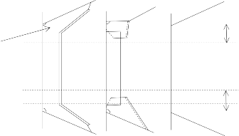
face plate X X
X X
![]()
D Zone 0.25h
C Zone h
X X
Typical 5 point pattern
X X B Zone 0.25h
X X A Zone ![]()
Typical Transverse Frame Non - Typical Transverse Frame
Guidance Relating to the Rules for the Classification of Steel Ships 2015 193
![]()
Pt 1 Classification and Surveys
Annex 1-5 Thickness Measurement Method for Hull Structural Member Pt 1, Annex 1-5
![]()
Table 20-2 Thickness measurements reports - CSR Ships
Table 20-2 is to be used to vessels built under IACS Common Structural Rules(Pt 11, Pt 12 or Pt 13)(i.e. CSR Ships)
TM1-DHT/BC/DSBC*(CSR)
Report on THICKNESS MEASUREMENT of ALL DECK PLATING / ALL BOTTOM PLATING / ALL SIDE SHELL PLATING*
STRAKE POSITION | ||||||||||||||||||
PLATE POSITION | No. or Letter | As Built Thk. mm | Voluntary Thickness Addition mm | Renewal Thickness mm (a) | Forward Reading | Aft Reading | Mean Remaining Corr. Addition, mm [(c1)+(c2)]/2 | |||||||||||
Gauged Thk. mm (b1) | Remaining Corr. Addition, mm (c1)=(b1)-(a) | Gauged Thk. mm (b2) | Remaining Corr. Addition, mm (c2)=(b2)-(a) | |||||||||||||||
P | S | P | S | P | S | P | S | P | S | |||||||||
15th forward | ||||||||||||||||||
14th | ||||||||||||||||||
13th | ||||||||||||||||||
12th | ||||||||||||||||||
11th | ||||||||||||||||||
10th | ||||||||||||||||||
9th | ||||||||||||||||||
8th | ||||||||||||||||||
7th | ||||||||||||||||||
6th | ||||||||||||||||||
5th | ||||||||||||||||||
4th | ||||||||||||||||||
3rd | ||||||||||||||||||
2nd | ||||||||||||||||||
1st | ||||||||||||||||||
Amidships | ||||||||||||||||||
1st aft | ||||||||||||||||||
2nd | ||||||||||||||||||
3rd | ||||||||||||||||||
4th | ||||||||||||||||||
5th | ||||||||||||||||||
6th | ||||||||||||||||||
7th | ||||||||||||||||||
8th | ||||||||||||||||||
9th | ||||||||||||||||||
10th | ||||||||||||||||||
11th | ||||||||||||||||||
12th | ||||||||||||||||||
13th | ||||||||||||||||||
14th | ||||||||||||||||||
15th | ||||||||||||||||||
Ship's Name : Class Identity No. : Report No. :
Operators Signature : (NOTES)
1. This report form is to be used for recording the thickness measurement of : All strength deck plating within the cargo (length) area
All keel, bottom shell plating and bilge plating within the cargo (length) area
Side shell plating including selected wind and water strakes outside cargo (length) area
All wind and water strakes within cargo (length) area
2. The strake position is to be clearly indicated as follow :
2.1 For strength deck indicate the number of the strake of plating inboard from the stringer plate.
2.2 For bottom plating indicate the number of the strake of plating outboard from the keel plate.
2.3 For side shell plating give number of the strake of plating below sheerstrake and letter as shown on shell expansion.
3. For BC/DSBC(CSR), only the deck plating strakes outside line of openings are to be recorded.
4. Measurements are to be taken at the forward and aft areas of all plates and where plates cross ballast and cargo tank/hold boundaries separate measurements for the area of plating in way of each type of tank/hold are to be recorded.
5. The single measurements recorded are to represent the average of multiple measurements.
6. The remaining corrosion addition is to be recorded with result of gauged thickness minus renewal thickness. If the result is negative, the structure in way shall be renewed, and the mark "R" is to be indicated in the right-hand column. If the result is between 0 and 0.5 mm (0 included), the structure in way shall be additional gauged, and the mark "S" is to be indicated in the right-hand column.
* DHT BC DSBC
: delete as appropriate
: Double Hull Oil Tankers with ESP notation
: Bulk Carriers with ESP notation
: Double Skin Bulk Carriers with ESP notation
194 Guidance Relating to the Rules for the Classification of Steel Ships 2015
![]()
Pt 1 Classification and Surveys
Annex 1-5 Thickness Measurement Method for Hull Structural Member Pt 1, Annex 1-5
![]()
Table 20-2 Thickness measurements reports - CSR Ships
TM2-DHT/BC/DSBC*(CSR)(i)
(continued)
Report on THICKNESS MEASUREMENT OF SHEERSTRAKE AND DECK PLATING AT TRANSVERSE SECTIONS
(one, two or three transverse sections)
STRENGTH DECK AND SHEERSTRAKE PLATING | ||||||||||||||||||||||||||||||
FIRST TRANSVERSE SECTION AT FRAME NUMBER : | SECOND TRANSVERSE SECTION AT FRAME NUMBER : | THIRD TRANSVERSE SECTION AT FRAME NUMBER : | ||||||||||||||||||||||||||||
STRAKE POSITION | No. or Letter | As Built Thk. mm | Vol. Thk. Add. mm | Ren. Thk. mm (a) | Gauged Thk. mm (b) | Remaining Corr. Addition, mm (b)-(a) | No. or Letter | As Built Thk. mm | Vol. Thk. Add. mm | Ren. Thk. mm (a) | Gauged Thk. mm (b) | Remaining Corr. Addition, mm (b)-(a) | No. or Letter | As Built Thk. mm | Vol. Thk. Add. mm | Ren. Thk. mm (a) | Gauged Thk. mm (b) | Remaining Corr. Addition, mm (b)-(a) | ||||||||||||
P | S | P | S | P | S | P | S | P | S | P | S | |||||||||||||||||||
Stringer Plate | ||||||||||||||||||||||||||||||
1st strake inboard | ||||||||||||||||||||||||||||||
2nd | ||||||||||||||||||||||||||||||
3rd | ||||||||||||||||||||||||||||||
4th | ||||||||||||||||||||||||||||||
5th | ||||||||||||||||||||||||||||||
6th | ||||||||||||||||||||||||||||||
7th | ||||||||||||||||||||||||||||||
8th | ||||||||||||||||||||||||||||||
9th | ||||||||||||||||||||||||||||||
10th | ||||||||||||||||||||||||||||||
11th | ||||||||||||||||||||||||||||||
12th | ||||||||||||||||||||||||||||||
13th | ||||||||||||||||||||||||||||||
14th | ||||||||||||||||||||||||||||||
centre strake | ||||||||||||||||||||||||||||||
sheer strake | ||||||||||||||||||||||||||||||
TOPSIDE TOTAL | ||||||||||||||||||||||||||||||
Ship's Name : Class Identity No. : Report No. :
Operators Signature : (NOTES)
1. This report form is to be used for recording the thickness measurements of :
- Strength deck plating and sheerstrake plating transverse sections :
One, two or three sections within the cargo (length) area comprising of the following structural items :
(1) Strength deck plating
(2) Stringer plate
(3) Sheerstrake
2. For BC/DSBC(CSR), only the deck plating strakes outside line of openings are to be recorded.
3. The topside area comprises deck plating, stringer plate and sheerstrake (including rounded gunwales)
4. The exact frame station of measurement is to be stated.
5. The single measurements recorded are to represent the average of multiple measurements.
6. The remaining corrosion addition is to be recorded with result of gauged thickness minus renewal thickness. If the result is negative, the structure in way shall be renewed, and the mark "R" is to be indicated in the right-hand column. If the result is between 0 and 0.5 mm (0 included), the structure in way shall be additional gauged, and the mark "S" is to be indicated in the right-hand column.
* : delete as appropriate
Guidance Relating to the Rules for the Classification of Steel Ships 2015 195
![]()
Pt 1 Classification and Surveys
Annex 1-5 Thickness Measurement Method for Hull Structural Member Pt 1, Annex 1-5
![]()
Table 20-2 Thickness measurements reports - CSR Ships
TM2-DHT/BC/DSBC*(CSR)(ii)
(continued)
Report on THICKNESS MEASUREMENT OF SHELL AND BOTTOM PLATING AT TRANSVERSE SECTIONS
(one, two or three transverse sections)
Ship's Name : Class Identity No. : Report No. :
SHELL AND BOTTOM PLATING | ||||||||||||||||||||||||||||||
FIRST TRANSVERSE SECTION AT FRAME NUMBER : | SECOND TRANSVERSE SECTION AT FRAME NUMBER : | THIRD TRANSVERSE SECTION AT FRAME NUMBER : | ||||||||||||||||||||||||||||
STRAKE POSITION | No. or Letter | As Built Thk. mm | Vol. Thk. Add. mm | Ren. Thk. mm (a) | Gauged Thk. mm (b) | Remaining Corr. Addition, mm (b)-(a) | No. or Letter | As Built Thk. mm | Vol. Thk. Add. mm | Ren. Thk. mm (a) | Gauged Thk. mm (b) | Remaining Corr. Addition, mm (b)-(a) | No. or Letter | As Built Thk. mm | Vol. Thk. Add. mm | Ren. Thk. mm (a) | Gauged Thk. mm (b) | Remaining Corr. Addition, mm (b)-(a) | ||||||||||||
P | S | P | S | P | S | P | S | P | S | P | S | |||||||||||||||||||
1st below sheer strake | ||||||||||||||||||||||||||||||
2nd | ||||||||||||||||||||||||||||||
3rd | ||||||||||||||||||||||||||||||
4th | ||||||||||||||||||||||||||||||
5th | ||||||||||||||||||||||||||||||
6th | ||||||||||||||||||||||||||||||
7th | ||||||||||||||||||||||||||||||
8th | ||||||||||||||||||||||||||||||
9th | ||||||||||||||||||||||||||||||
10th | ||||||||||||||||||||||||||||||
11th | ||||||||||||||||||||||||||||||
12th | ||||||||||||||||||||||||||||||
13th | ||||||||||||||||||||||||||||||
14th | ||||||||||||||||||||||||||||||
15th | ||||||||||||||||||||||||||||||
16th | ||||||||||||||||||||||||||||||
17th | ||||||||||||||||||||||||||||||
18th | ||||||||||||||||||||||||||||||
19th | ||||||||||||||||||||||||||||||
20th | ||||||||||||||||||||||||||||||
keel strake | ||||||||||||||||||||||||||||||
BOTTOM TOTAL | ||||||||||||||||||||||||||||||
Operators Signature :
(NOTES)
1. This report form is to be used for recording the thickness measurements of :
- Shell and bottom plating transverse sections :
One, two or three sections within the cargo (length) area comprising of the following structural items :
(1) Side shell plating
(2) Bilge plating
(3) Bottom shell plating
(4) Keel plate
2. The bottom area comprises keel, bottom and bilge plating.
3. The exact frame station of measurement is to be stated.
4. The single measurements recorded are to represent the average of multiple measurements.
5. The remaining corrosion addition is to be recorded with result of gauged thickness minus renewal thickness. If the result is negative, the structure in way shall be renewed, and the mark "R" is to be indicated in the right-hand column. If the result is between 0 and 0.5 mm (0 included), the structure in way shall be additional gauged, and the mark "S" is to be indicated in the right-hand column.
* : delete as appropriate
196 Guidance Relating to the Rules for the Classification of Steel Ships 2015
![]()
Pt 1 Classification and Surveys
Annex 1-5 Thickness Measurement Method for Hull Structural Member Pt 1, Annex 1-5
![]()
Table 20-2 Thickness measurements reports - CSR Ships
TM3-DHT/BC/DSBC*(CSR)
(continued)
Report on THICKNESS MEASUREMENT OF LONGITUDINAL MEMBERS AT TRANSVERSE SECTIONS
(one, two or three transverse sections)
Ship's Name : Class Identity No. : Report No. :
FIRST TRANSVERSE SECTION AT FRAME NUMBER : | SECOND TRANSVERSE SECTION AT FRAME NUMBER : | THIRD TRANSVERSE SECTION AT FRAME NUMBER : | ||||||||||||||||||||||||||||
STRUCTURE MEMBER | No. or Letter | As Built Thk. mm | Vol. Thk. Add. mm | Ren. Thk. mm (a) | Gauged Thk. mm (b) | Remaining Corr. Addition, mm (b)-(a) | No. or Letter | As Built Thk. mm | Vol. Thk. Add. mm | Ren. Thk. mm (a) | Gauged Thk. mm (b) | Remaining Corr. Addition, mm (b)-(a) | No. or Letter | As Built Thk. mm | Vol. Thk. Add. mm | Ren. Thk. mm (a) | Gauged Thk. mm (b) | Remaining Corr. Addition, mm (b)-(a) | ||||||||||||
P | S | P | S | P | S | P | S | P | S | P | S | |||||||||||||||||||
Operators Signature :
(NOTES)
1. This report form is to be used for recording the thickness measurements of :
- Longitudinal members at transverse sections :
One, two or three sections within the cargo (length) area comprising of the following structural items :
For DHT(CSR) For BC/DSBC(CSR)
(1) | Deck longitudinals | (1) | Deck longitudinals |
(2) | Sheerstrake longitudinals | (2) | Deck girders |
(3) | Side shell longitudinals | (3) | Sheerstrake longitudinals |
(4) | Bilge longitudinals | (4) | Topside tank sloping plate |
(5) | Bottom longitudinals | (5) | Topside tank sloping plate longitudinals |
(6) | Deck girders | (6) | Bottom longitudinals |
(7) | Horizontal girders in wing ballast tanks | (7) | Bottom girders |
(8) | Bottom girders | (8) | Bilge longitudinals |
(9) | Longitudinal bulkhead top strake | (9) | Side shell longitudinals, if any |
(10) | Longitudinal bulkhead bottom strake | (10) | Inner bottom plating |
(11) | Longitudinal bulkhead plating (remainder) | (11) | Inner bottom longitudinals |
(12) | Longitudinal bulkhead longitudinals | (12) | Hopper plating |
(13) | Inner side plating | (13) | Hopper longitudinals |
(14) | Inner side longitudinals | (14) | Inner side plating |
(15) | Hopper plating | Inner side longitudinals, if any | |
(16) | Hopper longitudinals | Horizontal girders in wing ballast tanks | |
(17) | Inner bottom plating | ||
(18) | Inner bottom longitudinals | ||
(19) | Topside tank plating | ||
(20) | Topside tank longitudinals |
2. The exact frame station of measurement is to be stated.
3. The single measurements recorded are to represent the average of multiple measurements.
4. The remaining corrosion addition is to be recorded with result of gauged thickness minus renewal thickness. If the result is negative, the structure in way shall be renewed, and the mark "R" is to be indicated in the right-hand column. If the
result is between 0 and 0.5 mm (0 included), the structure in way shall be additional gauged, and the mark "S" is to be indicated in the right-hand column.
* : delete as appropriate
Guidance Relating to the Rules for the Classification of Steel Ships 2015 197
![]()
Pt 1 Classification and Surveys
Annex 1-5 Thickness Measurement Method for Hull Structural Member Pt 1, Annex 1-5
![]()
Table 20-2 Thickness measurements reports - CSR Ships
TM4-DHT/BC/DSBC*(CSR)
(continued)
Report on THICKNESS MEASUREMENT OF TRANSVERSE STRUCTURAL MEMBERS
in the cargo oil and ballast tanks within the cargo tank length / in the double bottom, hopper side and topside ballast tanks*
Ship's Name : Class Identity No. : Report No. :
TANK DESCRIPTION : | ||||||||||
LOCATION OF STRUCTURE : | ||||||||||
STRUCTURAL MEMBER | ITEM | As Built Thickness mm | Voluntary Thickness Addition mm | Renewal Thickness mm (a) | Gauged Thickness mm (b) | Remaining Corr. Addition mm (b)-(a) | ||||
P | S | P | S | |||||||
Operators Signature :
(NOTES)
1. This report form is to be used for the following structural items :
recording the thickness measurements of transverse structural members comprising of
For DHT(CSR) For BC/DSBC(CSR)
(1) Deck transverses - centre tank
(2) Deck transverses - wing tank
(3) Vertical web in wing ballast tank
(4) Doble bottom floors - wing tank
(5) Doble bottom floors - centre tank
(6) Longitudinal bulkhead vertical webs
(7) Cross ties
(1) Doble bottom tank floors
(2) Topside tank transverses
(3) Hopper side tank transverses
(4) Transverse web frame
Ordinary transverse frame in double skin tank
2. The single measurements recorded are to represent the average of multiple measurements.
3. The remaining corrosion addition is to be recorded with result of gauged thickness minus renewal thickness. If the result is negative, the structure in way shall be renewed, and the mark "R" is to be indicated in the right-hand column. If the result is between 0 and 0.5 mm (0 included), the structure in way shall be additional gauged, and the mark "S" is to be indicated in the right-hand column.
* : delete as appropriate
198 Guidance Relating to the Rules for the Classification of Steel Ships 2015
![]()
Pt 1 Classification and Surveys
Annex 1-5 Thickness Measurement Method for Hull Structural Member Pt 1, Annex 1-5
![]()
Table 20-2 Thickness measurements reports - CSR Ships
TM5-DHT/BC/DSBC*(CSR)
(continued)
Report on THICKNESS MEASUREMENT OF W.T/O.T TRANSVERSE BULKHEADS
within the cargo tanks/holds and ballast tanks
Ship's Name : Class Identity No. : Report No. :
TANK/HOLD DESCRIPTION : | |||||||||
LOCATION OF STRUCTURE : FRAME NO: | |||||||||
STRUCTURAL COMPONENT (PLATING/STIFFENER) | As Built Thickness mm | Voluntary Thickness Addition mm | Renewal Thickness mm (a) | Gauged Thickness mm (b) | Remaining Corr. Addition mm (b)-(a) | ||||
P | S | P | S | ||||||
Operators Signature :
(NOTES)
1. This report form is to be used for recording the thickness measurement of W.T / O.T transverse bulkheads within the cargo tanks/holds and ballast tanks including bulkhead stiffeners and internal stiffeners of upper and lower stools.
2. The single measurements recorded are represent the average of multiple measurements.
3. The remaining corrosion addition is to be recorded with result of gauged thickness minus renewal thickness. If the
result is negative, the structure in way shall be renewed, and the mark "R" is to be indicated in the right-hand column. If the result is between 0 and 0.5 mm (0 included), the structure in way shall be additional gauged, and the mark "S" is to be indicated in the right-hand column.
* : delete as appropriate
Guidance Relating to the Rules for the Classification of Steel Ships 2015 199
![]()
Pt 1 Classification and Surveys
Annex 1-5 Thickness Measurement Method for Hull Structural Member Pt 1, Annex 1-5
![]()
Table 20-2 Thickness measurements reports - CSR Ships
TM6-DHT/BC/DSBC*(CSR)
(continued)
Report on THICKNESS MEASUREMENT OF MISCELLANEOUS STRUCTURAL MEMBERS
STRUCTURAL MEMBER : | SKETCH | |||||||||
LOCATION OF STRUCTURE : | ||||||||||
Description | As Built Thk. mm | Voluntary Thickness Addition mm | Renewal Thickness mm (a) | Gauged Thickness mm (b) | Remaining Corr. Addition mm (b)-(a) | |||||
P | S | P | S | |||||||
Ship's Name : Class Identity No. : Report No. :
Operators Signature : (NOTES)
1. This report form is to be used for recording the thickness measurement of miscellaneous structural members including the following structural items :
(1) Hatch coamings (including stiffeners)
(2) Deck plating between hatches
(3) Hatch covers (including stiffeners)
(4) Inner bulkhead plating
(5) Superstructure deck plating
(6) Forepeak tank internal members
(7) Aftpeak tank internal members
2. The single measurements recorded are to represent the average of multiple measurements.
3. The remaining corrosion addition is to be recorded with result of gauged thickness minus renewal thickness. If the result is negative, the structure in way shall be renewed, and the mark "R" is to be indicated in the right-hand column. If the result is between 0 and 0.5 mm (0 included), the structure in way shall be additional gauged, and the mark "S" is to be indicated in the right-hand column.
* : delete as appropriate
200 Guidance Relating to the Rules for the Classification of Steel Ships 2015
![]()
Pt 1 Classification and Surveys
Annex 1-5 Thickness Measurement Method for Hull Structural Member Pt 1, Annex 1-5
![]()
Table 20-2 Thickness measurements reports - CSR Ships
TM7-BC(CSR)
(continued)
Report on THICKNESS MEASUREMENT OF CARGO HOLD TRANSVERSE FRAMES
CARGO HOLD NO. : | |||||||||||||||||||||||||||
UPPER PART | MID PART | LOWER PART | |||||||||||||||||||||||||
FRAME NUMBER | As Built Thk. mm | Vol. Thk. Add. mm | Ren. Thk. mm (a) | Gauged Thk. mm (b) | Remaining Corr. Addition, mm (b)-(a) | As Built Thk. mm | Vol. Thk. Add. mm | Ren. Thk. mm (a) | Gauged Thk. mm (b) | Remaining Corr. Addition, mm (b)-(a) | As Built Thk. mm | Vol. Thk. Add. mm | Ren. Thk. mm (a) | Gauged Thk. mm (b) | Remaining Corr. Addition, mm (b)-(a) | ||||||||||||
P | S | P | S | P | S | P | S | P | S | P | S | ||||||||||||||||
Ship's Name : Class Identity No. : Report No. :
Operators Signature : (NOTES)
1. This report form is to be used for recording the thickness measurement of : Cargo hold transverse frames or diaphragms
2. The location and pattern of measurements is to be indicated on the sketches of hold frames shown below.

3. The single measurements recorded are to represent the average of multiple measurements.
4. The remaining corrosion addition is to be recorded with result of gauged thickness minus renewal thickness. If the result is negative, the structure in way shall be renewed, and the mark "R" is to be indicated in the right-hand column. If the result is between 0 and 0.5 mm (0 included), the structure in way shall be additional gauged, and the mark "S" is to be indicated in the right-hand column.
* : delete as appropriate ![]()
Guidance Relating to the Rules for the Classification of Steel Ships 2015 201
![]()
Pt 1 Classification and Surveys
Annex 1-6 Areas of Close-up Survey, etc. Pt 1, Annex 1-6
![]()
Annex 1-6 Areas of Close-up Survey, etc.
1. Guidance for areas of Close-up Survey for General Dry Cargo Ships, Bulk Carriers, Oil Tankers, Chemical Tankers, Double Hul Oil Tankers and Double Skin Bulk Carriers specified in Table 1.2.8,
Table 1.3.1, Table 1.3.4, Table 1.3.7, Table 1.3.10 and Table 1.3.13 of
diagrams as follows.
the Rules are indicated on the
(1) Areas of Close-up Survey for General Dry Cargo Ships
202 Guidance Relating to the Rules for the Classification of Steel Ships 2015
Pt 1 Classification and Surveys
Annex 1-6 Areas of Close-up Survey, etc. Pt 1, Annex 1-6
![]()
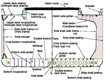
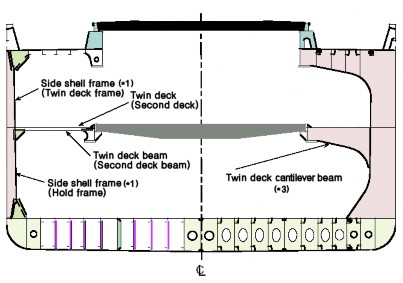
Note : (*1) through (*6) are as given in Table 1.2.8 of the Rules
Guidance Relating to the Rules for the Classification of Steel Ships 2015 203
Pt 1 Classification and Surveys
Annex 1-6 Areas of Close-up Survey, etc. Pt 1, Annex 1-6
![]()
(2) Areas of Close-up Survey for Bulk Carriers with ESP notation

204 Guidance Relating to the Rules for the Classification of Steel Ships 2015
Pt 1 Classification and Surveys
Annex 1-6 Areas of Close-up Survey, etc. Pt 1, Annex 1-6
![]()
(3) Areas of Close-up Survey for Oil Tankers with ESP notation
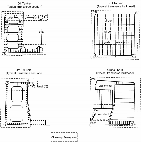
Note : (*1) through (*5) are as given in Table 1.3.4 of the Rules.
Guidance Relating to the Rules for the Classification of Steel Ships 2015 205
Pt 1 Classification and Surveys
Annex 1-6 Areas of Close-up Survey, etc. Pt 1, Annex 1-6
![]()
(4) Areas of Close-up Survey for Chemical Tankers with ESP notation
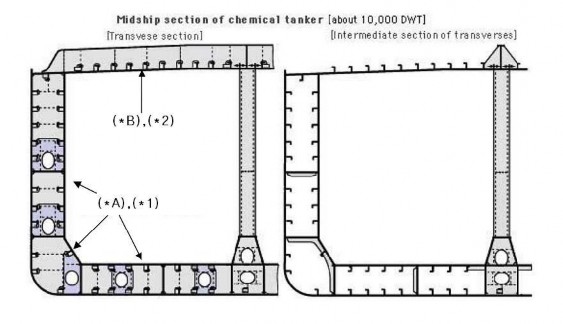
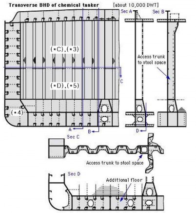
206 Guidance Relating to the Rules for the Classification of Steel Ships 2015
Pt 1 Classification and Surveys
Annex 1-6 Areas of Close-up Survey, etc. Pt 1, Annex 1-6
![]()
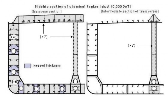
Note : (*1) through (*7) and (*A) through (*D) are as given in Table 1.3.7 of the Rules.
Guidance Relating to the Rules for the Classification of Steel Ships 2015 207
Pt 1 Classification and Surveys
Annex 1-6 Areas of Close-up Survey, etc. Pt 1, Annex 1-6
![]()
(5) Areas of Close-up Survey for Double Hull Oil Tankers with ESP notation
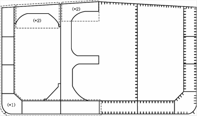
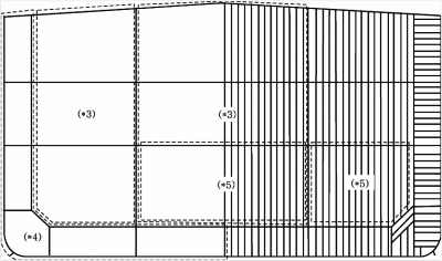
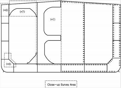
Note : (*1) through (*7) are as given in Table 1.3.10 of the Rules.
208 Guidance Relating to the Rules for the Classification of Steel Ships 2015
Pt 1 Classification and Surveys
Annex 1-6 Areas of Close-up Survey, etc. Pt 1, Annex 1-6
![]()
(6) Areas of Close-up Survey for Double Skin Bulk Carriers with ESP notation
Guidance Relating to the Rules for the Classification of Steel Ships 2015 209
Pt 1 Classification and Surveys
Annex 1-6 Areas of Close-up Survey, etc. Pt 1, Annex 1-6
![]()
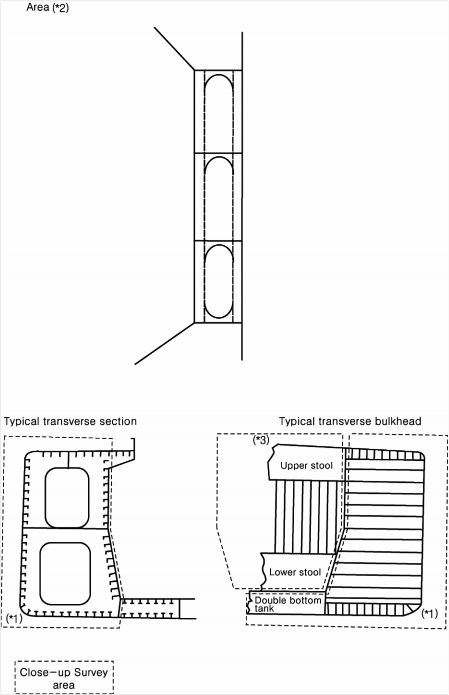
Note : (*1) through (*5) are as given in Table 1.3.13 of the Rules
210 Guidance Relating to the Rules for the Classification of Steel Ships 2015
Pt 1 Classification and Surveys
Annex 1-6 Areas of Close-up Survey, etc. Pt 1, Annex 1-6
![]()
2. The typical midship sections of liquefied gas carriers specified in indicated on the diagrams as follows.
Table 1.2.10
of the Rules are
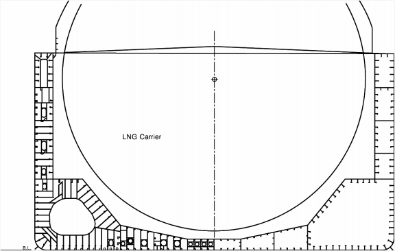
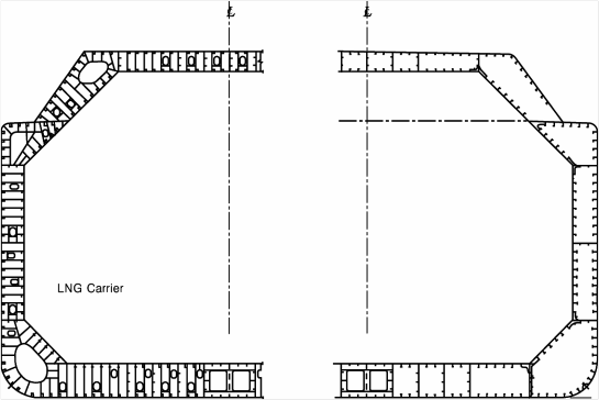
Guidance Relating to the Rules for the Classification of Steel Ships 2015 211
Pt 1 Classification and Surveys
Annex 1-6 Areas of Close-up Survey, etc. Pt 1, Annex 1-6
![]()
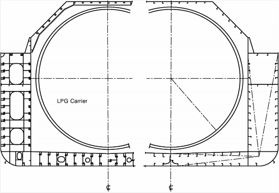
![]()
212 Guidance Relating to the Rules for the Classification of Steel Ships 2015
Pt 1 Classification and Surveys
Annex 1-7 Continuous Machinery Survey Procedure(CMS) Pt 1, Annex 1-7
![]()
Annex 1-7 Continuous Machinery Survey Procedure(CMS)
1. Application of CMS
(1) Where the CMS system is intended to be applied, the Shipowner is to submit the "Application for CMS" including "CMS programme". The CMS system, in principle, is applied to machinery installation items of established type. However, the CMS system is not to be applied to non- propelled vessels unless special consideration is given by the Society. And the CMS pro- gramme is to be complied with the requirements as follows,
(A) In principle, all items for CMS are to be included in the programme.
(B) Consecutive survey intervals of each item are not to exceed 5 years. And all items are to be examined in rotation.
(C) Preferably, open-up schedules of machinery installations are to be planned to enable the at-
tending Surveyor to evaluate the condition of the whole system from the open-up results of any survey.
(D) The CMS programme above may be replaced with reference to the ship's maintenance
programme. In cases where the ship's maintenance programme is modified in the process of implementation, the CMS programme on board may be partially or wholly amended.
(2) On the basis of the "CMS Programme" submitted by the Shipowner, the Society is to prepare
the CMS status, thereafter. the CMS status is to be forwarded from the Head Office to the Shipowner after the completion of CMS. The CMS up-date status is to be kept on board for reference by the attending Surveyor.
(3) Items covered by the CMS system are, in principle, those shown in Table 1 of the Guidance.
(4) In principle, it is preferable to conduct the open-up survey of essential auxiliaries(normally pro- vided in duplicate or more) alternately at similar intervals. However, the surveys of diesel en-
gines driving generators and bilge pumps is to be conducted, as far as practicable, simultaneous
with the Special Survey or Intermediate Survey.
(5) When defects are found on a part during survey, a thorough examination may be required on
other similar parts of machinery installations despite the "CMS programme" schedule.
2. Confirmatory Survey for CMS inspected by the Chief Engineer
(1) Qualification of Chief Engineer
(A) The Chief Engineer is to have sailing experience of at least 3 years as a chief engineer or be certified as a first-grade engineer by the relevant government and
(B) The Chief Engineer has at least 1 year sailing experience on a ship installed with a similar type of propulsion engine(internal combustion engine or steam turbine for main propulsion).
(2) Where CMS permissible for the Chief Engineer's inspection are as given in Table 2 were over-
hauled(or open up) at sea and inspected by the Chief Engineer in routine maintenance works, the inspections may be accepted for the CMS. Whenever such an inspection was carried out by the Chief Engineer during the ship's stay in port(where the attendance of the Society's Surveyor
is not easily available), the same process as above is applicable.
(3) The confirmatory survey by the Surveyor, in principle, is to be carried out within 5 months of the day when the CMS were inspected by the Chief Engineer under the attending Surveyor
as follows,
(A) inspection of operational condition.
(B) reviewing relevant details puter outputs) and hears and checking of oil and
of the engine log book or maintenance record(e.g. acceptable com- the Chief Engineer's opinion. If review of the relevant log book oil filter conditions indicate they are in good working condition,
these may substitute for the open up survey of machinery installations listed below. Substitute items are to be recorded in the survey report.
(a) Oil pumps(excluding cargo oil pumps) and oil heaters
(b) Hydraulic pumps and motors for deck machinery
![]()
(c) Oil tanks (having a capacity of 1 m or less)
Guidance Relating to the Rules for the Classification of Steel Ships 2015 213
Pt 1 Classification and Surveys
Annex 1-7 Continuous Machinery Survey Procedure(CMS) Pt 1, Annex 1-7
![]()
(C) Reporting submitted by the Chief Engineer including following contents
(a) Signature and license number of the Chief Engineer
(b) Inspection date and place
(c) Inspection items and results.
(D) If necessary, the attending Surveyor may request the overhauling(or open-up) survey of rele- vant machinery according to the results of the Confirmatory Survey.
3. Unification of names and numbers for CMS items
(1) If there are items of CMS used for same purpose each ship, their names are to be unified in accordance with Table 3.
(2) For items of CMS used for same purpose are provided in duplicate or more on board, if their serial numbers are not assigned or uncertain, it is recommended for shipyard or shipowner to
assign as belows, however, at existing ship the serial numbers of CMS
ones attached to name plates or using name on board.
(A) Numbering from Starboard to Port
(B) Numbering from Fore to After.
(C) Numbering from Upper to Lower.
(3) In case ships not applied to the CMS, (2) above may be applied to.
are to be identified with
214 Guidance Relating to the Rules for the Classification of Steel Ships 2015
Pt 1 Classification and Surveys
Annex 1-7 Continuous Machinery Survey Procedure(CMS) Pt 1, Annex 1-7
![]()
Table 1 Items Covered by the CMS System
Items | Details |
1. Main diesel engines | (a) Cylinder covers, cylinder liners, pistons (including piston pins and piston rods), crossheads (including pins, bearings and guides), connecting rods, crank shafts and bearings, camshafts and their driving gears, turbo chargers, scavenge air pumps or blowers, air intercoolers, attached essential pumps (bilge, lubricating oil, fuel oil and cooling water) |
2. Main steam turbines | (a) Turbine rotors, blades, bearings, casings, nozzles, nozzle valves and maneuvering valves |
3. Power transmission systems and shafting systems | (a) Reduction gears, reversing gears, clutches and flexible couplings (b) Intermediate shafts, thrust shafts and their bearings |
4. Auxiliary engines | (a) Auxiliary engines driving generators (excluding emergency generators) or auxiliary essential machinery are to be handled in accordance with the requirements applicable to main engines. |
5. Auxiliary machinery | (a) Air compressors and blowers: main and auxiliary starting air compressors (excluding those for emergency use), air compressors for control system, forced draft fans for main boilers, gas compressors and gas blowers (b) Pumps for essential uses: - Cooling fresh water pumps, cooling sea water pumps, fuel oil pumps and lubricating oil pumps for main and auxiliary engines - Fuel oil pumps, feed water pumps and water circulating pumps for main boilers - Feed water pumps and water circulating pumps for auxiliary boilers - Thermal oil pumps- Condensing pumps for main engine - Sea water service pumps - Lubricating oil pumps for reduction gears - Lubricating oil pumps for stern tubes - Hydraulic oil pumps for controllable pitch propellers - Hydraulic oil pumps for steering gears - Hydraulic oil pumps for windlass and mooring winches - Bilge pumps (excluding those for oil separators), ballast pumps and fire pumps (excluding emergency fire pumps) - Cargo oil pumps (including chemical pumps and liquefied gas pumps), stripping pumps, spray pumps and tank cleaning pumps (c) Windlass and mooring winches (d) Cargo refrigerating installations (excluding those for provision storage): compressors, pumps, evaporators and condensers (e) Fresh water generators for main boilers (f) Fuel oil heaters (excluding those for purifiers) and tank cleaning heaters (g) Condensers and feed water heaters (h) Coolers (excluding those for air compressors) (i) Inert gas systems (j) Air reservoirs (excluding those for emergency use) and other pressure vessels for essential uses (k) Fuel oil tanks not form a part of the ship's structure (l) Other items considered to be applicable under the CMS by the Society |
Guidance Relating to the Rules for the Classification of Steel Ships 2015 215
![]()
Pt 1 Classification and Surveys
Annex 1-7 Continuous Machinery Survey Procedure(CMS) Pt 1, Annex 1-7
![]()
![]()
Table 2 Machinery Permissible for the Chief Engineers Inspection, etc.
Items | Remarks | |
Machinery permissible for the Chief Engineers inspection | 1. Main diesel engine 2. Auxiliary diesel engine(Refer to remarks) 3. Forced draft fans & burning pumps for main boiler 4. Auxiliary machinery (1) Air compressor (2) Auxiliary blower (3) Pump (4) Heat exchanger (5) Portable fuel oil tank (6) Fresh water generator (7) Deck machinery (8) Hydraulic pumps of steering gears However, for each part of the main internal combustion engine and internal combustion engine to drive main generator among machinery permissible for the Chief Engineer's inspection, open-up survey by the Surveyor for at least one of two CMS cycles is to be carried. | The Chief Engineer's inspection for auxiliary diesel engines The engine is completely opened up and a careful examination is made on all cylinder units, cylinder liners, cylinder covers, cylinder cover valves, pis- tons, piston rings, connecting rods and top and lower bearings, piston pins, camshaft driving gears, turbo-chargers, air-intercoolers, crankcase and crankcase doors, engine foundation bolts, and crank case safety valves. The top halves of all main bearings are removed and two bottom halves are taken out for examination. An examination is made on all crankpins and journals to detect cracks, especially at fillet and areas in the vicinity of oil holes and crank shaft oil grooves. Crank web deflections are measured and recorded. Wear downs of the cylinder liners are measured and recorded. The L.O. cooler attached to the engine, L.O. pumps, cooling water pumps, etc. of direct driv- en- type are opened up and examined. Verify through performance tests that safety de- vices are in good operating condition. The service hours of crank pin bolts are checked and recorded. |
Machinery impermissible for the Chief Engineers inspection | 1. Crank shaft, crank pin bearing and journal bearing of main engine, crank pin bolts and camshaft driven equipment(Refer to remarks) 2. Steam turbine (main, auxiliary, etc.) 3. Power transmission gear 4. Shafting arrangements 5. Air reservoir 6. Other items not applied to CMS by the Society (1) Refrigeration installations for pro- vision storage (2) Electrical installations (3) Boiler (4) Cargo handling gears(cargo winch) (5) Spare parts (6) Emergency compressors, emer- gency air tank, emergency gen- erators, emergency fire pumps, etc. (7) Steering gears (8) Other items not considered sub- ject to CMS by the Society | Measurement of crank web deflection for main diesel engine and check of foundation bolts |
216 Guidance Relating to the Rules for the Classification of Steel Ships 2015
![]()
Pt 1 Classification and Surveys
Annex 1-7 Continuous Machinery Survey Procedure(CMS) Pt 1, Annex 1-7
![]()
Table 3 Table for Unified Name of Machinery
* The following unified expressions will be used in the Society's same purpose but are variously named from ship to ship.
CMS system for the machinery which has the
System | Unified name of machinery to be used in CMS system | Various names of machinery actually used in ships |
Cooling Sea Water System | Main Cooling S.W. Pump | - Main Cooling S.W. Pump - Main Condenser Cooling S.W. Pump |
Reserve Cooling S.W. Pump | - Reserve Cooling S.W. Pump - Stand-by Cooling S.W. Pump | |
A/E Cooling S.W. Pump | - A/E Cooling S.W. Pump - Aux. Machinery Cooling S.W. Pump - Aux. G/T Cooling S.W. Pump | |
Aux. Condenser Cooling S.W. Pump | - Aux Condenser Cooling S.W. Pump - Dumping Condenser Cooling S.W. Pump - Vacuum Condenser Cooling S.W. Pump - Atmospheric Condenser Cooling S.W. Pump - Drain Cooler Cooling S.W. Pump | |
M/E F.W. Generator(Cooling) S.W Pump | ||
S.W. Circulating Pump | ||
I.G.G Cooling Water Pump | ||
Sea Water Service System | S.W. Service Pump | |
Cooling Fresh Water System | M/E Cooling F.W. Pump | - M/E Cooling F.W. Pump - Main Cooling F.W. Pump |
M/E Reserve Cooling F.W. Pump | - Reserve Cooling F.W. Pump - Cooling F.W. Service Pump | |
Aux. Cooling F.W. Pump | - Aux Cooling F.W. Pump - Air Intercooler Cooling F.W. Pump - Turbo Charger Cooling F.W. Pump | |
M/E Jacket Cooling F.W. Pump | ||
M/E Piston Cooling F.W. Pump | ||
Central Cooling F.W. Pump | ||
A/E Cooling F.W. Pump | - A/E Cooling F.W. Pump - Harbour Cooling F.W. Pump | |
Fuel Oil System | M/E F.O.V. Cooling Pump | - M/E F.O.V. Cooling Pump - M/E F.O.V. Cooling F.W (or Oil) Pump |
A/E F.O.V. Cooling Pump | ||
M/E F.O. Supply/Booster Pump | ||
M/E F.O. Supply pump | - M/E F.O. Supply Pump - Main H.F.O. Supply pump - Main I.F.O. Supply pump - Main M.D.O. Supply pump - Reserve F.O. Supply pump - F.O. Feed pump - Res. F.O. Supply & F.O. Valve Cooling pump - F.O. Supply & F.O. Transfer pump - Stand-by F.O. Supply Pump | |
M/E F.O. Booster Pump | ||
M/E F.O. Service Pump | - M/E F.O. Service Pump - M/E C Oil Service Pump | |
A/E F.O. Supply Pump | ||
A/E F.O. Service Pump | - A/E F.O. Service Pump - A/E C Oil Service Pump |
Guidance Relating to the Rules for the Classification of Steel Ships 2015 217
![]()
Pt 1 Classification and Surveys
Annex 1-7 Continuous Machinery Survey Procedure(CMS) Pt 1, Annex 1-7
![]()
Table 3 Table for Unified Name of Machinery (continued)
System | Unified name of machinery to be used in CMS system | Various names of machinery actually used in ships |
Fuel Oil System (Cont’d) | D.O. Service Pump | - D.O. Service Pump - A Oil Service Pump |
F.O. Transfer Pump | - F.O. Transfer Pump - C Oil Transfer Pump - H.F.O. Transfer Pump - I.F.O. Transfer Pump - F.O. Shift Pump - F.O. Transfer & Shift Pump - H.F.O. & M.D.O. Transfer Pump | |
D.O. Transfer Pump | - D.O. Transfer Pump - A Oil Transfer Pump - M.D.O. Transfer Pump | |
M/E F.O. Circulating Pump | - F.O. Circulating Pump - F.O. Recycle Pump | |
Main Boiler F.O. Service Pump | - Boiler F.O. Service Pump - Boiler F.O. Feed Pump - Boiler F.O. Supply Pump - Boiler F.O. Transfer Pump | |
Main Boiler D.O. Service Pump | - Boiler D.O. Service Pump - Boiler D.O. Feed Pump - Boiler D.O. Supply Pump - Boiler D.O. Transfer Pump | |
Main Boiler Burning Pump | - Boiler Burning Pump - Boiler Pilot Burner F.O. Pump | |
Lub. Oil System | M/E L.O. Pump | |
A/E L.O. Pump | - A/E L.O. Pump - A/E Reserve L.O. Pump - A/E L.O. Service Pump | |
M/E Reserve L.O. Pump | - Reserve L.O. Pump - Aux. L.O. Pump - Stand-by L.O. Pump | |
M/E L.O. Service Pump | - L.O. Service Pump - Rocker Arm L.O. Pump - Priming L.O. Pump | |
M/E Crosshead L.O. Pump | ||
M/E Camshaft L.O. Pump | ||
M/E Piston rod Stuffing Box L.O. Pump | ||
M/E Turbo-charger L.O. Pump | ||
Reduction Gear L.O. Pump | ||
L.O. Transfer Pump | - L.O. Transfer Pump - L.O. Shift Pump | |
Stern Tube L.O. Pump | - Stern Tube L.O. Pump - Forward Seal Cooling L.O. Pump - After Seal Cooling L.O. Pump | |
C.P.P. Hyd. Oil Pump | ||
Bilge System | Bilge Pump | - Bilge Pump - Aux. Bilge Pump - Bilge & Sanitary Pump - Bilge Transfer Pump |
218 Guidance Relating to the Rules for the Classification of Steel Ships 2015
![]()
Pt 1 Classification and Surveys
Annex 1-7 Continuous Machinery Survey Procedure(CMS) Pt 1, Annex 1-7
![]()
Table 3 Table for Unified Name of Machinery (continued)
System | Unified name of machinery to be used in CMS system | Various names of machinery actually used in ships |
Bilge System (Cont’d) | Fire & Bilge Pump | - Bilge & Fire Pump - Bilge, Fire & G.S. Pump - Bilge, Fire & Cooling S.W. Pump - Fire, G.S. & S.W. Service Pump - G.S. (& Fire) & Pump |
Bilge & Ballast (& Fire) Pump | - Bilge & Ballast Pump - Bilge, Ballast & Fire Pump - Bilge, Ballast (& Fire) & Cooling S.W. Pump | |
Ballast System | Ballast Pump | - Ballast Pump - Ballast & Cooling S.W. Pump - Ballast & G.S. Pump - Ballast & S.W. Service Pump |
Stripping Pump | ||
Heeling Pump | - Heeling Pump - Heeling & Trimming Pump | |
Feed Water System | Main Boiler Feed Water Pump | - Main Boiler Feed Water Pump - Exh. Gas Boiler Feed Water Pump - Exh. Gas Economizer Feed Water Pump - L.P. Steam Generator Feed Water Pump |
Aux. Boiler Feed Water Circulating Pump | - Aux. Boiler Feed Water Pump - Aux. Exh. Gas Economizer Feed Water Pump - Aux. L.P. Steam Generator Feed Water Pump | |
Main Boiler Water Circulating Pump | - Main Boiler Water Circulating Pump - Exh. Gas Boiler Water Circulating Pump - Exh. Gas Economizer Water Circulating Pump - Hot Water Circulating Pump | |
Aux. Boiler Water Circulating Pump | - Aux. Boiler Water Circulating Pump - Aux. Exh. Gas Boiler Water Circulating Pump - Aux. Exh. Gas Economizer Water Circulating Pump - Hot Water Circulating Pump | |
Main Condensate Pump | ||
Condensate Pump for Aux. Turbine | ||
Reserve Condensate Pump | - Reserve Condensate Pump - Aux. Condensate Pump - Condensate & Drain Transfer Pump | |
Dump drain Transfer Pump | ||
Condenser Circulating Pump | - Condenser Circulating Pump - Vacuum Condenser Circulating Pump - Atmospheric Condenser Circulating Pump - Drain Cooler Circulating Pump - Aux. Condenser Circulating Pump | |
Fresh Water System | F.W. Generator for Main Boiler | |
Air System | Main Air Compressor | - Main Air Compressor - Main Engine Starting Air Compressor |
Reserve Air Compressor | - Aux. Air Compressor - Working Air Compressor - Topping up Air Compressor - Instrument Air Compressor - Reserve Air Compressor | |
Control Air Compressor |
Guidance Relating to the Rules for the Classification of Steel Ships 2015 219
![]()
Pt 1 Classification and Surveys
Annex 1-7 Continuous Machinery Survey Procedure(CMS) Pt 1, Annex 1-7
![]()
System
Table 3 Table for Unified Name of Machinery (continued) Unified name of machinery to be used in
CMS system Various names of machinery actually used in ships
- M/E Main Cooling F.W. Cooler
M/E Main Cooling F.W. Cooler
M/E Jacket Cooling F.W. Cooler M/E Piston Cooling F.W. Cooler
- Central F.W. Cooler
Fresh Water
A/E F.O.V. Cooling F.W. Cooler - F.O.V. F.W. Cooler
- Fuel Valve & Turbo Charger F.W. Cooler
Cooler
A/E F.O.V. Cooling F.W. Cooler
A/E Cooling F.W. Cooler
A/E Turbo-charger Cooling F.W. Cooler Exh. Valve Cooling F.W. Cooler
F.W. Cooler for Air Compressor M/E F.O.V. Cooling Oil Cooler A/E F.O.V. Cooling Oil Cooler
- F.O.V. & Exh. V. Cooling F.W. Cooler
M/E L.O. Cooler - M/E L.O. Cooler
- Main Turbine L.O. Cooler
A/E L.O. Cooler - A/E L.O. Cooler
- Aux. Turbine L.O. Cooler
Oil Cooler
M/E Turbo-charger L.O. Cooler A/E Turbo-charger L.O. Cooler Stern Tube L.O. Cooler Reduction Gear L.O. Cooler M/E Camshaft L.O. Cooler
C.P.P. Hyd. Oil Cooler
Aux. Turbine Condenser - Aux. Turbine Condenser
- G/T Condenser
- Aux. Atmospheric Condenser
Feed Water
Atmospheric Condenser
- Aux. Condenser
- Aux. Condenser & Drain Cooler
Cooler
Vacuum Condenser - Vacuum Condenser
Dump Condenser - Dump Condenser
- Drain Cooler
Oil Heater
Drain Cooler
Main Condenser M/E F.O. Heater A/E F.O. Heater
- Oil Heating Drain Cooler
Main Boiler F.O. Heater - Boiler F.O. Heater (Steam)
Thermal Oil
Aux. Boiler F.O. Heater
- Boiler F.O. Heater (Electric)
Heater Thermal Oil Heater
Main Boiler Feed Water Heater
- Aux. Feed Water Heater
Feed Water
Heater
Aux. Boiler Feed Water Heater
- Aux. Boiler Feed Water Heater
L.P. Feed Water Heater
Deaerator - Deaerator
Deaerating Feed Water Heater - Deaerating Feed Water Heater 1st Feed Water Heater
2nd Feed Water Heater 3rd Feed Water Heater 4th Feed Water Heater
220 Guidance Relating to the Rules for the Classification of Steel Ships 2015
![]()
Pt 1 Classification and Surveys
Annex 1-7 Continuous Machinery Survey Procedure(CMS) Pt 1, Annex 1-7
![]()
Table 3 Table for Unified Name of Machinery (continued)
System | Unified name of machinery to be used in CMS system | Various names of machinery actually used in ships |
Fresh Water Heater | Hot Water Heater | - Hot Water Heater - Calorifier |
Main Engine F.W. Heater | ||
Other Heat Exchanger | F.W. Generator for Main Boiler | |
Refrigerator Condenser | ||
Air Reservoir | Main Air Reservoir | - Main Air Reservoir - Main Engine Starting Air Reservoir |
A/E Air Reservoir | - Aux. Air Reservoir - Working Air Reservoir - Aux. Engine Starting Air Reservoir - Cargo Pump Engine Starting Air Reservoir - Em’cy Air Reservoir | |
Service Air Reservoir | ||
Control Air Reservoir | ||
F.O. Tank | M/E F.O. Settling Tank | - M/E F.O. Settling Tank - M/E H.F.O. Settling Tank - M/E I.F.O. Settling Tank - M/E M.D.O. Settling Tank |
M/E F.O. Service Tank | - M/E F.O. Service Tank - M/E H.F.O. Service Tank - M/E I.F.O. Service Tank - M/E M.D.O. Service Tank | |
A/E F.O. Settling Tank | - A/E F.O. Settling Tank - A/E A Oil Settling Tank | |
A/E F.O. Service Tank | - A/E F.O. Service Tank - A/E A Oil Service Tank - A/E F.O. Tank | |
Boiler F.O. Settling Tank | - Boiler F.O. Settling Tank - Boiler H.F.O. Settling Tank - Boiler M.D.O. Settling Tank | |
Boiler F.O. Service Tank | - Boiler F.O. Service Tank - Boiler H.F.O. Service Tank - Boiler M.D.O. Service Tank | |
D.O. Settling Tank | ||
D.O. Service Tank | ||
Cargo System | Cargo Pump | - Cargo (Oil) Pump - Cargo Pump (Motor) - Aux. Cargo Pump - Cargo & Ballast Pump |
Stripping Pump | ||
Spray Pump | ||
Pump in Pump Room | Ballast Pump in Pump Room | |
Clean Ballast Pump in Pump Room | ||
Ballast Pump in FWD. Pump Room(or F’CLE) | - Ballast Pump in FWD. Pump Room - Ballast Pump in F’CLE | |
Bilge Pump | ||
S.W. Service Pump |
Guidance Relating to the Rules for the Classification of Steel Ships 2015 221
![]()
Pt 1 Classification and Surveys
Annex 1-7 Continuous Machinery Survey Procedure(CMS) Pt 1, Annex 1-7
![]()
Table 3 Table for Unified Name of Machinery (continued)
System | Unified name of machinery to be used in CMS system | Various names of machinery actually used in ships |
Tank Cleaning System | Tank Cleaning Pump | - Tank Cleaning Pump - Butterworth Pump - Tank Cleaning & Fire Pump - Butterworth & Tank Cleaning Pump - Tank Cleaning & Bilge, Fire, (G.S.) Pump - Butterworth & Bilge, Fire, (G.S.) Pump |
Tank Cleaning Heater | - Tank Cleaning Heater - Butterworth heater | |
Tank Cleaning Drain Cooler | - Tank Cleaning Drain Cooler - Butterworth Drain Cooler | |
Other Machinery in Pump Room | Ventilation Fan | |
Deck Machinery | Hyd. Pump for Steering Gear | |
Windlass | ||
Mooring Winch | - Mooring Winch - Auto Tension Winch | |
Hyd. Pump for Deck Machinery | ||
Capstan | ||
Cargo Refrigerating Machinery | Compressor | |
Condenser Cooling Pump | - Condenser Cooling Pump - Ref. Cooling S.W. (or F.W.) Pump - Ref. & Aux. Cooling S.W. (or F.W.) Pump | |
Brine Pump | ||
Refrigerant Pump | ||
Condenser | ||
Evaporator | ||
Evaporator Cooling S.W. Pump | ||
Machinery for Gas Carrier | Gas Compressor | |
High Duty Compressor | ||
Low Duty Compressor | ||
Vacuum Pump | ||
Main Vaporizer | ||
Forced Vaporizer | ||
Boil-off/Warm-up Heater | ||
Vent Gas Heater | ||
N2 Generator Unit | ||
N2 Buffer Tank | ||
Inert Gas Generator | ||
Cargo Heating Drain Cooler | ||
Glycol Water Steam Heater | ||
Glycol Water Electric Heater | ||
Glycol Water Circulating pump |
![]()
222 Guidance Relating to the Rules for the Classification of Steel Ships 2015
![]()
Pt 1 Classification and Surveys
Annex 1-8 Planned Maintenance System Procedure(PMS) Pt 1, Annex 1-8
![]()
Annex 1-8 Planned Maintenance System Procedure(PMS)
1. General
(1) At the request of Owner, PMS is to be approved by the Society in accordance with Fig 1 and Information and Documents given in Table 1 including the following items are to be submitted.
(A) organization chart identifying areas of responsibility
(B) documentation filling procedures
(C) listing of equipment to be considered by the Society in PMS
(D) machinery identification procedure
(E) preventing maintenance sheets for each machine to be considered
(F) listing and specifications of condition monitoring equipment
(G) baseline data for equipment with condition monitoring,
(H) listing and schedule of preventive maintenance procedure.
(2) In addition to the above documentation the following information shall be available on board:
(A) the above (1) in an up-to-date fashion
(B) maintenance inspection(manufacturer's and shipyard's)
(C) condition monitoring data including all data since last opening of the machine and the origi- nal base line data
(D) reference documentation (trend investigation procedure etc.)
(E) records of maintenance including repairs and renewals carried out.
(3) An annual report covering the year's service, including the following information, shall be re- viewed by the Society:
(A) clauses (1) (C), (D), (E) and (G) as well as changes to other clause in the above (1)
(B) clause (2) (C)
(C) full trend analysis(including spectrum analysis for vibrations) of machinery displaying operat-
ing parameters exceeding acceptable tolerances.
(4) In general, the intervals for PMS shall not exceed those specified for CMS. However, for com- ponents where the maintenance is based on running hours longer intervals may be accepted as
long as the intervals are based on the manufacturer's recommendations. However, if an approved
condition monitoring system is in effect, the machinery survey intervals based on CMS cycle period may be extended
(5) The PMS shall be programmed and maintained by a computerized system. However, this may not be applied to the current already approved schemes. Computerized systems shall include back-up devices, such as disks/tapes, CDs, which are to be updated at regular intervals.
2. Chief Engineer's responsibility of PMS.
(1) Where a chief engineer is entitled to be complied with the following requirements, the Society is to issue the Chief Engineer Qualification Certificate.
(A) First-grade licence issued in the relevant nation is to be provided.
(B) To be recommended by the shipowner(or ship management company) and approved by the Society.
(2) The chief engineer shall be the responsible person on board in charge of the PMS.
(3) Documentation on overhauls of items covered by the PMS shall be reported and signed by the chief engineer.
(4) Access to computerized systems for updating of the maintenance documentation and maintenance
program shall only be permitted by the chief engineer or other authorized person.
(5) PMS items to be maintained by Chief Engineer is to be complied with Table 2 and to be re- tained on board the overhauled(or opened up) records. However, PMS items not permitted by
Chief Engineer's records in Table 2 are to be surveyed under the attending surveyor as far as
practicable at Annual Survey.
Guidance Relating to the Rules for the Classification of Steel Ships 2015 223
Pt 1 Classification and Surveys
Annex 1-8 Planned Maintenance System Procedure(PMS) Pt 1, Annex 1-8
![]()
3. Condition monitoring system(CM)
(1) When it is ascertained that the ship under the approved PMS has been installed with condition monitoring system, the inspection for the following items has been confirmed by the Surveyor at the periodical survey, the overhaul(or open-up) intervals on the PMS may be extended. However, the (B) below are to be submitted to the Surveyor.
(A) Conditions and functions of condition monitoring equipment.
(B) Measurements and analysis results obtained from condition monitoring equipment for each
machine to be considered.(Refer to Table 3)
(C) Operating condition of each equipment
(2) Where the measurements and analysis results obtained from the previous paragraph are to be re-
viewed and they are found in unsatisfactory by the Surveyor, overhauling(or opening up) nation may be requested.
exami-
(3) The
out.
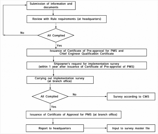
Implementation Survey after installation of the condition monitoring system is to be carried
Fig 1 Flow chart for approval procedures
224 Guidance Relating to the Rules for the Classification of Steel Ships 2015
Pt 1 Classification and Surveys
Annex 1-8 Planned Maintenance System Procedure(PMS) Pt 1, Annex 1-8
![]()
Table 1 Information and Documents to be submitted
Name and content | Remarks |
(1) Machinery inventory content: Listing of machinery subjected to maintenance, and index or code for each machinery. | Unify classification nomenclature for machi- nery to use the same names as far as possible. machinery index or code and CMS code. Identify and mark items not permitted by the chief engineer. |
(2) Maintenance schedule: (A) It is to be stated for PMS of each item of machinery as follows: - Identification of overhaul survey, kind of inspection and test and content of measurement record - Intervals of overhaul survey, inspection and measure- ment (B) It is to be stated for CM as follows: - Layout of CM, maker, model and specification of CM equipment - Measuring points, names of measuring instruments and measuring parameters for each machinery - Intervals of measurement for each machinery - Acceptable limits for monitored condition for each machinery - Examples of input and output data | To be satisfied the Rules requirements for overhaul survey, inspection, measurement, etc. of all machinery. To be overhauled with period not to exceed 5 year To be confirmed that quantity of machinery to be surveyed every year is not less than about 20 % of machinery covered by PMS. To be reviewed CM layout and feasibility of measuring parameters. To be sure that output format is easily rec- ognizable by the chief engineer. To be reviewed the feasibility of acceptable limit. |
(3) Reporting system: (A) To be stated in the program as follows: - Records of maintenance and repairs - Spare parts (B) A regular reporting system between the ship and the supporting land department of the ship company is to be stated. | Ease in confirming that all reporting and re- cording procedures are carried out exactly. |
(4) Documents for qualification requirements of the chief en- gineer: (A) Copy of chief engineer's licence (B) Chief engineer's resume | To be satisfied with the requirements of chief engineer's qualification. |
Guidance Relating to the Rules for the Classification of Steel Ships 2015 225
![]()
Pt 1 Classification and Surveys
Annex 1-8 Planned Maintenance System Procedure(PMS) Pt 1, Annex 1-8
![]()
Table 2 Machinery with permission of maintenance by the chief engineer in PMS
System | Machinery with permission of maintenance by the chief engineer under a PMS | Not permission of maintenance by the chief engineer but subject to the attending Surveyor. |
Main diesel engines | 1. Cylinder covers 2. Valves and valve gears 3. Cylinder blocks and liners 4. Pistons and piston rods 5. Connecting rods, crossheads, top end bearings, guides, gudgeon pins and bushes 6. Crankshafts and bearings 7. Scavenge pumps, blowers and air coolers 8. Camshafts and camshaft drives | 1. Relief devices(Crankcase, scavenging air cham- ber, camshaft driving gear room, etc.) 2. Engine trial 3. Holding down bolts and chocks |
Main Turbines | Casings, rotors, blades, bearing, nozzle, nozzle valve and control valve - with CM equipment whose monitoring of operat- ing parameters and vibration measurement is found in satisfactory under the attending Surveyor only. | 1. Holding down bolts and chocks 2. In case without CM equipment, it is to be surveyed after opening the top casing of turbine. |
Auxiliary Engines | Auxiliary engines, auxiliary steam turbines and their associated coolers and pumps. - But, where those are used for driving generator, only in case that power can be supplied by at least the other 1 set to essential auxiliaries neces- sary for propulsion and safety of ship and cool- ing of refrigerated cargo, in case where any 2 sets do not work(for example; where 1 set is stand- by during the period of 1 set maintenance). | Auxiliary internal combustion engines or auxil- iary steam turbines driving generators - In case of satisfying conditions in the left col- umn, the chief engineer's maintenance may be permitted. |
Shafting | 1. Intermediate shafts and bearings 2. Thrust shafts and bearing | 1. Reduction/increase gearing 2. Flexible couplings and clutches |
Remote Control and Automation System | Records for malfunction, abnormal alarms, etc., are to be made and submitted to the Society. | 1. Main engine control system for bridge, cen- tralized or automatic controls 2. Requirements for centralized controls or un- attended machinery automations |
Pressure vessels and auxiliaries | 1. Pumps attached to main engine(bilge, L.O., F.O. and cooling water) 2. Independently driven pumps(bilge, ballast, F.W. cooling, S.W. cooling, L.O. and F.O. transfer) 3. Coolers and condensers (F.W. and L.O. coolers for main engine, main and auxiliary condensers and drain coolers) 4. Heaters(F.O., L.O. and feed water) 5. Other auxiliaries(air compressors including safety devices, windlasses, mooring winches, forced or induced draft fans and Independent F.O. tanks) 6. Air reservoir | 1. First start arrangement trial 2. Piping arrangements: steam pipes, sea con- nections and valves, maneuvering valves, bulkhead stop valves, bilge check-stop valves (including foot valves) 3. Steering gear 4. Electrical equipment Others |
Others | IGS(scrubber units, blowers, independent gas gen- erating units) | IGS(all components for inert gas system except for items covered by the chief engineer's main- tenance) |
226 Guidance Relating to the Rules for the Classification of Steel Ships 2015
![]()
Pt 1 Classification and Surveys
Annex 1-8 Planned Maintenance System Procedure(PMS) Pt 1, Annex 1-8
![]()
Table 3 Machinery Operating Parameter for Condition monitoring System
Items | Operating Parameter |
Main Diesel Engine | 1. Shaft horse power 2. Engine and Shaft RPM 3. Cylinder pressure-time curves 4. Oil fuel injection pressure-time curves 5. Oil fuel temperature or viscosity 6. Charge air pressure 7. Exhaust gas temperatures 8. Engine cooling systems, temperatures and pressures 9. Engine lubricating oil system, temperatures and pressures 10. Turbo-charger RPM and vibration 11. Lubricating oil analysis data 12. Crankshaft deflections 13. Main bearing temperatures |
Main Steam Turbine | 1. Turbine rotor vibration 2. Turbine rotor axial displacement 3. Shaft horsepower 4. Shaft and turbine rotor FPM 5. Performance data; (1) Steam conditions at inlet and outlet of each turbine (2) Boiler performance data (3) Condenser vacuum (4) Sea temperatures (5) Steam conditions of other major steam consuming auxiliaries |
Auxiliary Steam Turbine | Same as main steam turbine |
Auxiliary Diesel Engine | 1. Exhaust gas temperatures 2. Engine cooling systems temperatures and pressures 3. Engine L.O. system; temperatures and pressures 4. Turbo-charger RPM and vibration 5. Lub. oil analysis data 6. Crankshaft deflections |
Auxiliaries | 1. Cooler efficiency, inlet and outlet temperatures 2. Heater temperatures 3. Pumps and fans; vibration and performance 4. Differential pressure across filters |
![]()
Guidance Relating to the Rules for the Classification of Steel Ships 2015 227
![]()
Pt 1 Classification and Surveys
Annex 1-9 Guidance for Survey of Waterjet Propulsion Systems and Azimuth or Rotatable Thruster Pt 1, Annex 1-9
![]()
Annex 1-9 Guidance for Survey of Waterjet Propulsion Systems and Azimuth or Rotatable Thruster
1. The surveys for waterjet propulsion systems and azimuth or rotatable thruster are to comply with the following requirements.
(1) Waterjet propulsion systems
(A) Annual Surveys
At each Annual Survey, the following surveys and inspections are to be carried out.
(a)
(b)
(c)
(d)
General inspection of the propulsion system Verification test of steering performance
Operation test of the reverser
General inspection of impeller
(B) Intermediate Surveys
At each Intermediate Survey, in addition to the all requirements for Annual Survey, the sur- veys and inspections are to be carried out as deemed necessary by the Surveyor.
(C) Special Surveys
At each Special Survey, in addition to the all requirements for Intermediate Survey, open-up inspections for major part of the hydraulic pump are to be carried.
(D) Docking Surveys
At each Docking Survey, the following surveys and inspections are to be carried out.
(a) The wearing condition of the bearing is to be verified with means deemed appropriate
by the Society.
(b)
(c)
(d)
General inspection of the forward sealing device
General inspection of the impeller
Deflector and reverser are to be inspected.
(E) Main Shaft Surveys
(a) After drawing out the main shaft, the condition of the main shaft are to be examined.
Where "drawing out" means preparing to be able to sufficiently examine the condition of the main shaft.
(b)
(c)
(d)
General General
General
inspection of coupling bolts
inspection of the major parts of the forward and after main shaft bearings inspection of the major parts of the forward main shaft sealing assembly
(e)
(f)
(g)
Open-up inspection for thrust bearing
Inspection of the contact faces of the impeller boss and main shaft(when installed with key and spline)
General inspection of the impeller
(2) Azimuth or rotatable thruster
(A) Periodical Surveys and Docking Surveys
The relevant provisions for propeller shaft, propeller, steering gear and stern tube sealing de-
vice specified in Ch 2, Sec 2 through Sec 7 of the Rules are to be applied with the nec- essary modifications.
(B) Shaft Surveys and Gear unit open-up Surveys
Inspections and surveys specified in the following (a) through (b) are to be carried out.
(a)
(b)
(c)
(d)
Open-up inspection for propeller shaft sealing device
Efficient crack detection specified in Ch 2, 702. 4 and 5 of the Rules
General examination for each bearing Open- up inspection for gear unit
2. For the items which are not specified in Par 1 above, the relevant provisions for propeller shaft, propeller, steering gear and stern tube sealing device specified in Ch 2, Sec 2 through Sec 7 of the Rules, are to be applied with the necessary modifications. ![]()
228 Guidance Relating to the Rules for the Classification of Steel Ships 2015
Pt 1 Classification and Surveys
Annex 1-10 Loading Instrument on Stability Pt 1, Annex 1-10
![]()
Annex 1-10 Loading Instrument on Stability
1. Application
(1) This requirement applies to ships having a length exceeding 24 metres when a loading instru- ment with a stability computation capability(hereinafter called "loading instrument on stability") is installed on a new ship or newly installed on an existing ship in accordance with the re- quirement in Ch 1, 307. of the Rules.
(2) For the purpose of this requirements, "new ship" means a ship for which the application for Classification Survey during Construction is made on or after 1 January 1997 and "existing
ship" means a ship for the application January 1997.
for Classification Survey during Construction before 1
2. Approval procedure
(1) The procedure for approval of a loading instrument on stability is as illustrated in Fig 1.
Submit User's Manual and Test conditions
Design Approval of the Software, if requested
Approval of User's Manual and Test conditions
Approval Data or Calculation output by the Society
On-board Installation Test
Issue Certificate of Loading Instrument
* The approval of the software should be carried out in accordance with "Guidance for Approval of Manufacturing Process and Type Approval, Etc."
Fig 1 Procedure for the approval of loading instrument on stability for a specific ship.
(A) User's operations manual and 3 copies of test conditions are to be submitted to Head Office. The loading instrument on stability may be approved provisionally if the stability in- formation booklet is approved provisionally. A provisional certificate may be issued after on- board installation in this case.
(B) The requirements which are checked during approval of the user's operation manual and test conditions are as follows:
- the output of the loading instrument for the exampled test conditions are correct.
- the technical contents and forms of the user's operations manual is appropriate.
(2) Where the loading instrument on stability is intended for office use on shore(in such case it
may be used for stability calculations for several different ships), this is acceptable provided that:
- the procedure in this appendix has been satisfactorily completed.
- the user's operations manual and test conditions have been approved for each of ships for which the instrument is used.
- operational performance of the hardware is to be tested but environmental testing is not nor- mally required.
- the installation test is to be carried out and a certificate is issued if found appropriate.
Guidance Relating to the Rules for the Classification of Steel Ships 2015 229
Pt 1 Classification and Surveys
Annex 1-10 Loading Instrument on Stability Pt 1, Annex 1-10
![]()
3. Software for a specific ship
(1) General
(A) In order to apply the design approved software to a specific ship, details of the test con- ditions prepared using all relevant data used by the ship designer concerning hull form defi-
nition and compartment definition is to be submitted.
(B) The calculation result should include at least 4 test loading conditions covering the antici-
pated loading draughts, i.e. a maximum loading draught, a light condition draught and two intermediate draughts. In order for the Society to check the correctness of the calculation,
the test conditions should be the same as presented in the stability information booklet sub-
mitted for approval. All test loading conditions must show all deadweight items and in- formation on the free surface effect for each deadweight item.
(C) The drawings and data required to be submitted by (2) and (3) below need not be sub- mitted if these are same that were submitted by the designers, etc.
(2) Intact Stability
(A) In order to the Society to verify the data submitted, the following information must be sub-
mitted:
- details of hull form definition, e.g., lines plans and/or offset tables, including all appendages.
- hydrostatic particulars including cross curve data
- details of compartment definition including list of volumes, center of gravity and free sur- face data
- details of position of down-flooding points.
- details of the relevant requirements and criteria against which the calculations must show compliance
- hard copy of output of results
(B) Hard copies of the full results for all test loading conditions are compared with the
![]()
Society's calculation result(or approved stability information booklet) and the hard copies should include displacement, draughts, trim, , , , free surface correction and an- gle of down flooding.
The residual ![]() distribution in curvilinear or tabulated form, is also to be produced for each case showing compliance with intact stability criteria.
distribution in curvilinear or tabulated form, is also to be produced for each case showing compliance with intact stability criteria.
(C) Hydrostatic and intact stability characteristics of the hull form and for each test loading con- dition produced by the software is to be checked against those derived by the Society's pro-
grams(or approved stability information booklet). Characteristics to be checked will include:
- hydrostatic properties for full range of service draughts
- cross curves of stability embracing full range of service displacements
- properties of fully complied test loading conditions
- compliance with intact stability criteria
![]()
- relevant limiting / / values for full range of service draughts where appropriate
(3) Grain stability
(A) In addition to the documentation as specified in preceding (2) (A), the following should al- so be submitted for the assessment of grain stability calculations.
- Cargo hold drawings showing the structure abreast and beyond hatched including details of hatch end beams with feeding holes, if fitted
- Hatch cover details
- Details of longitudinal divisions, if applicable
- Details of the relevant regulations and criteria against which the calculation must show compliance, e.g., International Grain Code in addition to relevant intact stability criteria
- Hard copy of output of results
(B) Hard copies of the full results for all test loading conditions are to be submitted so that de-
![]()
tailed comparisons may be made with the results from the Society's loading instrument pro- gram(or approved grain stability booklet). The output is to be include displacement, draughts, trim, , , , free surface correction, angle of down flooding, grain heeling mo-
ments and maximum allowable grain heeling moment. The residual ![]() distribution, curvi- linear or tabulated form, is also to be produced for each case showing compliance
distribution, curvi- linear or tabulated form, is also to be produced for each case showing compliance
with in-
230 Guidance Relating to the Rules for the Classification of Steel Ships 2015
Pt 1 Classification and Surveys
Annex 1-10 Loading Instrument on Stability Pt 1, Annex 1-10
![]()
(C) The results for each test condition produced by the software will be checked against those derived by the Society's programs(or approved grain stability booklet). The information to be assessed will include:
- curves or tables of grain heeling moments for every compartments, filled or partly filled, including the effects of temporary fittings
- tables of maximum permissible heeling moments or other information demonstrating com- pliance with the relevant requirements.
4. User's operations manual
(1) User's operations manual approved by the Society is to be provided for the loading instrument on stability. This manual should contain operating instructions for all stability calculations made by the loading instrument.
(2) The user's operations manual must be in a language readily understood by the users.
A English version, if not written in English language, should be provided if the ship on which the instrument is installed is engaged in the international voyage.
(3) The manual should contain general description of the stability software together with a full de-
scription of the operational procedure for stability calculations. In this connection, there should be a list of all terms, definitions, error messages and warnings likely to be encountered by the user.
In the case of error messages and warnings, there should be unambiguous user instructions for subsequent action to be taken in each case.
(4) In addition to the above, the following items should also be included in the user's operations
manual.
- Lightship weight and co-ordinates of center of gravity
- Full deadweight description of each test loading condition
- Details of applicable Codes/Conventions, including limiting values etc.
- An example of a non-standard calculation well supported by illustrations and sample instru- ment output
- Hard copy of the results of each test loading condition
- Details of the frequency of testing of the instrument(The loading instrument with a stability computation capability should be handled by qualified personnel fully familiar with the instru- ment and it is recommended that the correct functioning of the instrument be verified by the
ship's master at frequent intervals using the approved test conditions)
- Details of contingency measures in case of power failure
- Example printouts of every possible screen display, complete with explanatory text, to ensure that the user does not encounter any unfamiliar output
(5) In addition to the above, if the instrument performs also strength calculations, the manual
should contain permissible values for still water bending moments and cable, permissible local load for hatch covers, deck and double bottom
![]()
shear force and, structure, etc.
if appli-
Guidance Relating to the Rules for the Classification of Steel Ships 2015 231
Pt 1 Classification and Surveys
Annex 1-11 Procedural Requirements for Service Suppliers Pt 1, Annex 1-11
![]()
Annex 1-11 Procedural Requirements for Service Suppliers
1. General
The requirements in this Annex apply to assessment and approval of firms and laboratories provid- ing testing services(hereinafter referred to as the "supplier") who intend to supply a service (repairs, maintenance, inspection, tests, and measurements for survey) for a ship or mobile offshore (hereinafter referred to as the "ship") to be classed or have been classed to the Society and machi- nery, materials, etc (hereinafter referred to as the "products") which will be used on that ship.
(1) Firms engaged in thickness measurements on ships(except non-ESP ships less than 500 gross tonnage and all fishing vessels, and the separate requirements specified by the Society are to be applied to these ships)
(2) Firms engaged in tightness testing of hatches with ultrasonic equipment
(3) Firms carrying out in-water survey of ships and mobile offshore units
(4) Firms engaged in the examination of Ro-Ro ships bow, stern, side and inner doors
(5) Firms engaged in testing of coating systems in accordance with IMO Res.MSC.215(82)
(Performance Standard for Protective Coatings for Dedicated Seawater Ballast Tanks in All Type of Ships and Double-side Skin Spaces of Bulk Carriers) and IACS UI SC223 (For Application
of SOLAS Regulation II-1/3-2 Dedicated Seawater Ballast Tanks Carriers, adopted by Resolution
Performance Standard for Protective Coatings(PSPC) for in All Types of Ships and Double-side Skin Spaces of Bulk MSC.215(82))) and/or IMO Res.MSC.288(87) (Performance
Standard for Protective Coatings for Cargo Oil Tanks of Crude Oil Tankers)
(6) Other service firms
2. Procedure for approval and certification
(1) Document submission : The supplier is to submit a copy of the application together with two copies of each following data to the Society.
(A) Quality manual and/or documentary procedure covering following requirements:
(a) Code of conduct for the relevant activity
(b) Maintenance and calibration of equipment
(c) Training programmes for personnel(operators/technicians/inspectors)
(d)
(e)
(f)
(g)
(h)
(i)
Supervision and verification to ensure compliance with operational procedures Recording and reporting of information
Quality management of subsidiaries and agents
Job preparation
Periodic review of work process procedures, complaints, corrective actions and issuance, maintenance and control of documents
A documented quality system in compliance with the most current version of (KS A)ISO 9000 series and including the above items, (a) to (h), would be considered
acceptable.
(B) Outline of company(e.g. organization and management structure including subsidiaries to be included in the approval/certification)
(C) List of nominated agents, if any
(D) Experience of the company in the specific service area, if any
(E) List of personnel documented training and experience within the relevant service area, and qualifications according to recognised national, international or industry standards, as relevant
(F) Description of equipment used for the particular service for which approval is sought and a guide for operators of such equipment
(G) Check lists and record formats of the Society for reporting results of the services
(H) Evidence of approval/acceptance by other bodies or other class, if any
(I) Information on the other activities which may present a conflict of interest, if any
(J) Record of customer claims and of corrective actions requested by certification bodies, if any
(K) Where relevant, list and documentation of licenses granted by equipment's manufacturer
(L) Other data deemed necessary by the Society for the approval
232 Guidance Relating to the Rules for the Classification of Steel Ships 2015
Pt 1 Classification and Surveys
Annex 1-11 Procedural Requirements for Service Suppliers Pt 1, Annex 1-11
![]()
(2) Review and audit
(A) Documentation assessment
In the documentation assessment, the data submitted are investigated to confirm that the
documents are in conformity with the requirements in Par 2 (1) above.
(B) Field assessment
(a) Upon satisfactory outcome of the assessment of the documentation, a visit is made to evaluate the supplier's workshop(laboratory. etc.) and to verify the followings
(i) The supplier is duly organised and managed in accordance with the submitted
documents.
(ii) It is considered in conformity with requirements in Par 3, 4 & 5 and capable of conducting the services for which approval/certification is sought.
(b)
(c)
(d)
When parts of services are produced by subcontractors, the Society may request the as-
sessment of them for the purpose of confirming their Quality Control Standard.
When an external person takes part in a service relating to quality of products at works, the Society may request the assessment of that person.
When deficiencies are found, the supplier who is informed of such by documentation is to take the corrective action and report to the Society. Where deemed necessary, a visit
by the Surveyor may be made to evaluate the validity of the corrective action.
(C) Renewal audit
(a) Renewal audit is to be carried out in accordance with (A) and (B) above before the ex- piry date of the Approval Certificate.
(b) Where deemed acceptable, the part of data to be submitted and an audit may be reduced.
(D) Occasional audit
(a) The Society may request the occasional audit if any of the following condition occurs:
(i) When important changes are made to the approved quality system
(ii) When services which were approved are changed or added
(b) In the occasional audit, it is to be confirmed by the Society that all the necessary re- quirement are in a satisfactory condition.
(E) Preparations for assessment and Others
(a) When the assessment is performed in accordance with the requirements specified in (A) through (D) above, the preparations are to be made by the supplier. On such occasions, service suppliers is also to be present at the assessment.
(b) In case necessary preparations have not been made or in case no responsible person is present at the assessment, the Society may suspend the assessment.
(3) Approval
Certification is conditional on a practical demonstration of the specific service performance as well as satisfactory reporting being carried out.
(A) Issuance of Approval Certificate
(a) Upon satisfactory completion of both the audit of the supplier and the demonstration test, if required, the Society issues the Certificate of Approval in accordance with the other requirements by the Society. The supplier is to be registered on the service suppli-
ers list of the Society. The Certificate is to clearly state that the type and scope of services and any limitations or restrictions imposed.
(b) Where several servicing stations are owned by a supplier, each station is to be assessed and approved except as specified in Par 4 (B) below.
(B) The term of validity for the Approval Certificate
(a)
(b)
(c)
The valid term of an approval certificate is 3 years from the date of the initial or the
renewal approval.
In case where the renewal assessment is carried out within 3 months before the expiry date, the valid term of the certificate is three(3) years from the expiry date.
In case where the extension of the valid term of the approval Certificate is requested by the supplier, the Society may extend the valid term within the period of three(3) months after expiration of the term of validity. However, in this case, the term of val-
idity for the renewed approval certificate is the next day of the expiry date of the pre- vious certificate.
Guidance Relating to the Rules for the Classification of Steel Ships 2015 233
Pt 1 Classification and Surveys
![]()
Annex 1-11 Procedural Requirements for Service Suppliers Pt 1, Annex 1-11
(C) Change in the quality assurance system
(a) In case where any change to the company organization, the quality manual, effect on the quality system, it is to be immediately communicated to the the supplier.
(b) Important changes having significant effect on the approved quality system lows:
(i) Overall alteration or abolition of the quality manual, etc.
(ii) Alteration of major management(Owner, director's committee, etc.)
(iii) Alteration of organization(consolidation of the quality system, etc.)
etc. having Society by
are as fol-
(iv) Alteration, abolition and transfer of the major facilities specified in quality manual
(D) Suspension and withdrawal of certification
(a) Where non-conformities in the approved quality system are found by the Surveyor, or where conditions for the issuance of the certificate or for its maintenance have deterio- rated, the supplier is to correct the non-conformities. Such corrections are to be verified
by the Society if necessary. In case corrective actions are not taken within the specified period, the Society may suspend the approved certificate for a given period. In case the corrective actions are not taken for the suspended period, the Society may withdraw the approval.
(b)
(c)
The Society can withdraw the approval if any of the following conditions occur:
(i) Where the important changes having significant effect on the quality system is not communicated to the Society.
(ii) Where the occasional audit or renewal audit is not carried out in the relevant period.
(iii) Where a request for withdrawal is made by the supplier.
(iv)Where the service is carried out improperly or the result of inspection is reported improperly, and where the fact that the services provided are not in compliance with the approval condition are ascertained.
(v) Where the approval fees are not paid. (vi)Where wilful acts or omissions are ascertained.
A supplier whose approval has been cancelled, may apply for re-approval provided that
the non-conformities which resulted in cancellation are corrected, and the Society is is- sue the approval certificate after it is confirmed that the corrective action has effectively been implemented.
3. General Requirements of the Suppliers
(A) Extent of approval
The supplier is to demonstrate, as required by (B) - (I), that it has the competence and control needed to perform the services for which approval is sought.
(B) Training of personnel
The supplier is responsible for the qualification and training of its personnel to a recognised national, international or industry standard as applicable. Where such standards do not exist,
the supplier is to define standards for the training and qualification of its personnel relevant
to the functions which are authorized to perform. The personnel is to also have an adequate experience and be familiar with the operation of any necessary equipment. The personnel is
to have a minimum of one(1) year on-the-job training or equivalent experience. Where it is
not possible to perform internal training, a program of external training may be considered as acceptable.
(C) Supervision
The supplier is to provide supervision for all services provided. The appointed supervisor is responsible for work performed and the final report. The responsible supervisor is to have
minimum of two(2) years experience as a personnel within the approved activity of the
supplier. For a supplier consisting of one person, that person shall meet the requirements of a supervisor.
(D) Personnel records
The supplier is to maintain the records of the approved personnel and submit them when the records are requested by the Surveyor. The record is to contain information on age, for- mal education, training and experience for the approved services.
234 Guidance Relating to the Rules for the Classification of Steel Ships 2015
Pt 1 Classification and Surveys
Annex 1-11 Procedural Requirements for Service Suppliers Pt 1, Annex 1-11
![]()
(E) Equipment and facilities
The supplier is to have the necessary equipments and facilities for the service. A record containing information on maintenance and calibration of the equipments used is to be maintained.
(F) Procedures
The supplier is to have documented work procedures covering all services supplied.
(G) Subcontractors
The supplier is to submit the information on agreements and arrangements to the Society, if any parts of the services provided are subcontracted. Particular emphasis shall be given to quality management by the supplier in following-up of such subcontracts. Subcontractors pro-
viding any other than subcontracted personnel or equipment shall also meet the requirements of Par 2 (1) (A) and Par 3.
(H) Verification
The supplier is to verify that the services provided are carried out in accordance with ap- proved procedures.
(I) Reporting
The report is to be prepared in a form acceptable to the Society and it shall include a copy of the Certificate of Approval of the Society.
(J) Quality system
The supplier is to have a documented system covering at least the items in Par 2 (1) (A)
(a) to (h).
4. Service Suppliers in Relations with the Equipment Manufacturer
(A) A company which works as a service station for manufacturer(s) of equipment(and as a service supplier in this field), is to be assessed by the manufacturer(s) and nominated as their agent. The manufacturer is to ensure that appropriate instruction manuals, material etc. are available for the agent as well as of proper training of the agent's technicians. Such suppliers is to be approved either on a case by case basis, or in accordance with (B).
(B) If a manufacturer of equipment(and service supplier) applies to the Society for inclusion of his nominated agents and/or subsidiaries in the approval, then he must have implemented a quality system certified in accordance with the most current version of (KS A)ISO 9000 ser- ies, with effective controls of his agents and/or subsidiaries, and when these agents/sub- sidiaries have an equally effective quality system complying with the relevant requirements specified in the most current version of (KS A)ISO 9000 series. Such approvals shall be based upon an evaluation of the quality system implemented by the parent company against the most current version of (KS A)ISO 9000 series. The Society may require follow-up to confirm adherence to this quality system by performing audits on such agents or subsidiaries against the most current version of (KS A)ISO 9000 series.
5. Special Requirements for Various Categories of Service Suppliers
(1) Firms engaged in thickness measurements on ships
(A) Extent of engagement
Thickness measurement of structural material of ships except non-ESP ships less than 500
gross tonnage and all fishing vessels, and the separate requirements specified by the Society are to be applied to these ships.
(B) Supervisor and Personnel
(a) The responsible supervisor and personnels shall be qualified according to a recognised national or international industrial Non-Destructive Examination Standard(e.g. EN 473 level II or ISO 9712 level II).
(b) The supervisor and personnel are to have adequate knowledge of the Ship structures suf- ficiently to select a representative position for each measurements.
(C) Equipment
On coated surfaces, instruments using pulsed echo technique(either with oscilloscope or digi- tal instruments using multiple echo, single crystal technique) are required. Single echo instru- ments may be used on un-coated surfaces, which have been cleaned and grinded.
Guidance Relating to the Rules for the Classification of Steel Ships 2015 235
Pt 1 Classification and Surveys
Annex 1-11 Procedural Requirements for Service Suppliers Pt 1, Annex 1-11
![]()
(D) Procedures
Documented work procedures are at least to contain information on survey preparation, se- lection and identification of test locations, surface preparation, protective coating preservation, calibration checks, and report preparation and content.
(E) Report
(a) The report is to be made on the basis of the Annex 1-5 of the Guidance.
(b) The report is to be documented and maintained by supplier for each separate ship with being signed by the Surveyor.
(2) Firms engaged in tightness testing of hatches with ultrasonic equipment
(A) Extent of engagement
The suppliers undertaking tightness tests of hatches by ultrasonic equipment as an alternative to hose testing with water.
(B) Personnel
The personnel is to have the following qualifications:
(a)
(b)
(c)
Have knowledge of different hatch designs, their functioning and sealing features Have experience with operation and maintenance of different hatch designs
Be able to document a theoretical and practical training onboard in using ultrasonic
equipment specified
(C) Equipment
The ultrasonic equipment to be used is to be type approved by the Society. It should be demonstrated for the Surveyor that the equipment is fit for the purpose of detecting leakages in hatch covers.
(D) Procedures
The supplier is to have documented work procedures including the manual for the ultrasonic
equipment specified, its adjustment, its maintenance, its operation and approval criteria.
(3) Firms carrying out in-water survey
(A) Extent of engagement
In-water survey of ships and mobile offshore units.
(B) Training of personnel
(a) The supplier is responsible for the qualification of his personnels and the diving equip-
ment utilized when carrying out survey.
(b)
(c)
Following knowledges for training of personnel are to be documented.
(i) Ship's underwater structure and appendages, tail shaft, propeller, rudder and its bear-
ings, etc.
(ii) Non-destructive testing in accordance with a recognised national or international in- dustrial NDT standard. This requirement only applies if an in-water survey company
performs non-destructive testing.
(iii) Bearing clearance measurements on rudders and tail shaft
(iv)Under-water video monitoring with TV-monitors on deck, as well as still picture
work
(v) Operation of under-water communication system
(vi)Special equipment and tools like hull cleaners, grinders, cutters, etc.
Plan for training of personnel
A plan for training of personnel in the reporting system should be included the minimum Rule requirements for relevant ship types, ship's underwater structure, measuring of bearing
clearances, the recognition of corrosion damage, buckling and deteriorated coatings, etc.
(C) Supervisor
The supervisor is to be qualified according to the supplier's general requirements and have minimum two(2) years experience as a personnel carrying out survey.
(D) Personnel carrying out survey
The personnel carrying out survey is to have at least one(1) year of experience as an assis-
tant personnel carrying out survey(minimum 10 different assignments).
236 Guidance Relating to the Rules for the Classification of Steel Ships 2015
Pt 1 Classification and Surveys
Annex 1-11 Procedural Requirements for Service Suppliers Pt 1, Annex 1-11
![]()
(E) Equipment
The followings are to be available:
(a)
(b)
(c)
(d)
(e)
(f)
Closed circuit colour television with sufficient illumination equipment Two-way communication between diver and surface staff
Video recording device connected to the closed circuit television Under water still photography camera
Equipment for carrying out thickness gauging, non-destructive testing and measurements
(e.g. clearances, indents, etc.) as relevant to the work to be performed.
Equipment for cleaning of the hull
(F) Procedures and guidelines
The supplier is to have documented operational procedures and guidelines for how to carry
out the survey and handle the equipment. These are to include:
(a)
(b)
(c)
Two-way communication between diver and surface staff Video recording and closed circuit television operation
Guidance of the diver along the hull to ensure complete coverage of the parts to be
surveyed
(G) Verification
The supplier must have the surveyor's verification of each separate job, documented in the report by his signature
(4) Firms engaged in the examination of Ro-Ro ships bow, stern, side and inner doors
(A) Extent of engagement
Inspection of securing and locking devices, hydraulic operating system, electric control sys- tem for the hydraulics, electric indicator systems, and supporting, securing and locking de- vices and tightness testing.
(B) The supplier is to be certified in accordance with the relevant requirements specified in the most current version of (KS A)ISO 9000 series.
(C) Reference documents
The supplier is to have access to SOLAS 1974 as amended and IACS UR Z24 (Survey Requirements for Shell and Inner Doors of Ro-Ro Ships), or its equivalent, by the Society.
(D) In addition to Par 3 (c), the Senior Service Engineer(Supervisor) is to have a minimum
two(2) years education from a technical school.
(E) Required Equipment
(a) For Inspection of Supporting Securing and Locking Devices, Hinges and Bearings.
(i) Equipment for measuring clearances(i.e. feeler gauges, vernier calipers, micrometers).
(ii) Non-destructive examination(i.e. dye penetrant, magnetic particle inspection)
(b)
(c)
(d)
For Tightness Testing
(i) Ultrasonic leak detector or equivalent
For Inspection of Hydraulic Operating System
(i) Pressure gauges
(ii) Particle counter for analysing the quality of hydraulic fluid For Inspection of Electric Control System and Indication System
(i) Digital multi-meter
(ii) Earth fault detector
(F) Procedures and Instructions
(a) The supplier is to have access to drawings and documents, including the Operating and
Inspection Manual.
(b)
(c)
The supplier is to have access to the service history of the doors.
The supplier is to use, complete and sign a checklist which has been found acceptable
by the Society.
(G) Report
(a) After completion of the inspection, the report for each separate ship is to be made and verified by the Supplier.
(b) The report is to be signed by the Surveyor, documented and maintained.
Guidance Relating to the Rules for the Classification of Steel Ships 2015 237
Pt 1 Classification and Surveys
Annex 1-11 Procedural Requirements for Service Suppliers Pt 1, Annex 1-11
![]()
(5) Firms engaged in testing of coating systems in accordance with IMO Res.MSC.215(82) and IACS UI SC223 and/or IMO Res.MSC.288(87)
(A) Laboratories
(a) Extent of Engagement
Testing of coating systems in accordance with IMO Res.MSC.215(82) and IACS UI SC223 and/or IMO Res.MSC.288(87)
(b)
(c)
(d)
The laboratory is to provide to the Society the following information:
(i) A detailed list of the Laboratory test equipment for the IMO Res.MSC.215(82) and/or Res.MSC.288(87) coating approval.
(ii) A detailed list of reference documents comprising a minimum those referred to in IMO Res.MSC.215(82) and/or Res.MSC.288(87) that are available in the laboratory.
(iii) Details of testing panel preparation, procedure of test panel identification, coating
application, test procedures and a sample test report.
(iv) Details of exposure method and site for weathering primed test panels.
(v) A sample daily or weekly log/form for recording test condition and observations in-
cluding unforeseen interruption of the exposure cycle with corrective actions.
(vi) Details of any sub-contracting agreements(if applicable).
(vii) Comparison test report with an approved coating system or laboratory if available.
Reporting - Reference is made to the following IACS Recommendations;
(i) Rec.101 : IACS Model Report for IMO Res.MSC.215(82) Annex 1 "Test Procedures for Coating Qualification"
(ii) Rec.102 : IACS Model Report for IMO Res.MSC.215(82) Annex 1 "Test Procedures for Coating Qualification", Section 1.7 - Crossover Test
Audit of the test laboratory is to be based on this procedure and the standards listed in
the IMO Res.MSC.215(82) and/or Res.MSC.288(87).
(6) Other service firms
Where the supplier providing the service other than (1) through (5) wishes to obtain the appro-
val of the Society, other specified requirements are to be applied. ![]()
238 Guidance Relating to the Rules for the Classification of Steel Ships 2015
Pt 1 Classification and Surveys
Annex 1-12 Hull Survey for Classification Survey during Construction Pt 1, Annex 1-12
![]()
Annex 1-12 Hull Survey for Classification Survey during Construction
1. Scope
The scope of this Annex includes the following main activities:
(1) Examination of the parts of the ship covered by classification rules and by applicable statutory regulations for hull construction, to obtain appropriate evidence that they have been built in compliance with the rules and regulations, taking account of the relevant approved drawings.
(2) Appraisal of the manufacturing, construction, control and qualification procedures, including welding consumables, weld procedures, weld connections and assemblies, with indication of rele- vant approval tests.
(3) Witnessing inspections and tests as required in the classification rules used for ship construction including materials, welding and assembling, specifying the items to be examined and/or tested and how(e.g. by hydrostatic, hose or leak testing, non destructive examination, verification of
geometry) and by whom.
(4) Appraisal of material and equipment used for ship construction and their inspection at works is not included in this Annex. Details of requirements for hull and machinery steel forgings and
castings and for normal and higher strength hull structural steel are given in IACS UR W7(Hull
and Machinery Steel Forging), W8(Hull and Machinery Steel Casting) and W11(Normal and High Strength Hull Structural Steels) respectively. Acceptance of these items is verified through
the survey process carried out at the manufacturer’s works and the issuing of the appropriate certificates.
2. Definitions
(1) The hull structure is defined as follows:
(A) hull envelope including all internal and external structures,
(B) superstructures, deckhouses and casings,
(C) welded foundations, e.g. main engine seatings,
(D) hatch coamings, bulwarks,
![]()
(E) all penetrations fitted and welded into bulkheads, decks and shell,
(F) tvhaelvefisttingasllofILaLllC c1o9n6n6e,ctiaosnsamtoendedk, si,tebmuslk. heads and shell, such as air pipes and ship side
(G) welded attachments to shell, decks and primary members, e.g. crane pedestals, bitts and bol- lards, but only as regards their interaction on the hull structure.
(2) Reference to documents also includes electronic transmission or storage.
(3) Definition of survey methods which the Surveyor is directly involved in: Patrol, Review,
Witness
(A) Patrol, the act of checking on an independent and unscheduled basis that the applicable processes, activities and associated documentation of the shipbuilding functions identified in Table 1 continue to conform to classification and statutory requirements.
(B) Review, the act of examining documents in order to determine traceability, identification and to confirm that processes continue to conform to classification and statutory requirements
(C) Witness is the attendance at scheduled inspections in accordance with the agreed Inspection
and Test Plans or equivalent to the extent necessary to check compliance with the survey requirements.
3. Applications
(1) This Annex covers the survey of all new construction of steel ships intended for classification and for international voyages except for:
(A) those defined in SOLAS I/3
(B) High Speed Craft as defined in I/1.3.1 of the 2000 High Speed Craft Code
(C) Mobile Offshore Drilling Units as defined in I/1.2.1 of the MODU Code
(2) This Annex covers all statutory items, relevant to the hull structure and coating, i.e. Load Line
and SOLAS Safety Construction.
Guidance Relating to the Rules for the Classification of Steel Ships 2015 239
Pt 1 Classification and Surveys
Annex 1-12 Hull Survey for Classification Survey during Construction Pt 1, Annex 1-12
![]()
(3) This Annex does not cover the manufacture of equipment, fittings and appendages regardless whether they are made inside or outside of the shipyard, examples being as follows. Evidence of acceptance shall be provided by accompanying documentation from class Surveyor at manu- facturer and verified at the shipyard:
(A) hatch covers,
(B) doors and ramps integral with the shell and bulkheads,
(C) rudders and rudder stock,
(D) all forgings and castings integral to the hull.
(4) This Annex applies to the installation into the ship, welding and testing of:
(A) the items listed in (3) above
(B) equipment forming part of the watertight and weather tight integrity of the ship.
(5) This Annex applies to the hull structures and coating constructed at any of the following:
(A) shipbuilder’s facilities,
(B) sub-contractors at the shipbuilder’s facilities,
(C) sub-contractors at their own facilities or at other remote locations
4. Qualification and monitoring of personnel
(1) Exclusive Surveyors of the Society, as defined in IACS PR5(Definition of Exclusive Surveyor and Non-Exclusive Surveyor and Procedure for Employment and Control of Non- Exclusive Surveyors), are to confirm through patrol, review and witness as defined in Par 2 (3), that the ships are built using approved plans in accordance with the relevant rules and statutory requirements. The Surveyors are to be qualified to be able to carry out the tasks and procedures are to be in place to ensure that their activities are monitored. Details are specified in PR6(Procedure for Activity Monitoring of Surveyors/ISM Code Auditor) and PR7(Procedure for Qualification and Training of Surveyors).
5. Survey of the hull structure
(1) Table 1 provides a list of surveyable items for the hull structure and coating covered by this Annex, including:
(A) description of the shipbuilding functions
(B) classification and statutory survey requirements
(C) survey method required for classification
(D) relevant IACS and statutory requirement references
(E) documentation to be available for the Surveyor during construction
(a) the shipbuilder is to provide the Surveyors access to documentation required by classi- fication, this includes documentation retained by the shipbuilder or other third parties
![]()
(b) the list of documents approved or reviewed by the Society for the specific new con- struction are as follows:
( ) plans and supporting documents ( ) examination and testing plans
( ) NDE plans
( ) welding consumable details
( ) welding procedure specifications ( ) welding plan or details
( ) welder’s qualification records
( ) NDE operator's qualification records
(F) Documents to be inserted into the ship construction file. Refer to Par 10 for details
(G) A list of specific activities which are relevant to the shipbuilding functions. This list is not
exhaustive and can be modified to reflect the construction facilities or specific ship type.
(2) Evidence is also to be made available, as required, by the shipbuilder, to the Surveyor whilst the construction process proceeds to prove that the material and equipment supplied to the ship
has been built or manufactured under survey relevant to the classification rules and statutory requirements.
240 Guidance Relating to the Rules for the Classification of Steel Ships 2015
Pt 1 Classification and Surveys
Annex 1-12 Hull Survey for Classification Survey during Construction Pt 1, Annex 1-12
![]()
6. Review of the construction facility
(1) The Society is to familiarize themself with the yard's production facilities, management processes and safety for consideration in complying with the requirements of Table 1 using “Shipyard re- view record” of Annex 1-12-1 or equivalent prior to any steelwork or construction taking place in the following circumstances:
(A) where the Society has none or no recent experience of the construction facilities ![]() typically
typically
after a one year lapse - or when significant new infrastructure has been added,
(B) where there has been a significant management or personnel re-structuring having an impact
on the ship construction process,
(C) or where the shipbuilder contracts to construct a vessel of a different type or substantially
different in design.
7. Newbuilding survey planning
![]()
(1) Prior to commencement of surveys for any newbuilding project, the Society is to discuss with the shipbuilder at a kick off meeting the items listed in Table 1. The purpose of the meeting is to agree how the list of specific activities shown in Table 1 is to be addressed. The meeting is to take into account the shipbuilder's construction facilities and ship type including the list of proposed subcontractors. A record of the meeting is to be made, based upon the contents of the Table 1 the Table 1 can be used as the record with comments made into the appropriate column. If the Society has nominated a Surveyor for a specific newbuilding project then the Surveyor is to attend the kick off meeting. The builder is to be asked to agree to undertake ad hoc investigations during construction where areas of concern arise and for the builder to agree to keep the Society advised of the progress of any investigation. Whenever an investigation is undertaken, the builder is to be requested, in principle, to agree to suspend relevant construction activities if warranted by the severity of the problem.
(2) The records are to take note of specific published Administration requirements and inter- pretations of statutory requirements.
(3) The shipyard shall be requested to advise of any changes to the activities agreed at the kick off
meeting and these are to be documented. E.g. if the shipbuilder chooses to use or change sub-contractors, or to incorporate any modifications necessitated by changes in production or in-
spection methods, rules and regulations, structural modifications, or in the event where increased inspection requirements are deemed necessary as a result of a substantial non-conformance or
otherwise.
(4) Shipbuilding quality standards for the hull structure during new construction are to be reviewed and agreed during the kick-off meeting. Structural fabrication is to be carried out in accordance
with IACS Recommendation 47, “Shipbuilding and Repair Quality Standard”, or a recognized
fabrication standard which has been accepted by the Society prior to the commencement of fab- rication/construction. The work is to be carried out in accordance with the Rules and under sur-
vey of the Society.
(5) The kick-off meeting may be attended by other parties(owner, administrations, etc.) as defined in IACS PR3(Transparency of Classification and Statutory Information) subject to agreement by the
shipbuilder.
(6) In the event of series ship production consideration may be given to waiving the requirement for a kick off meeting for the second and subsequent ships provided any changes are docu-
mented as required in (1) and (3) above.
8. Examination and test plan for newbuilding activities
(1) The shipbuilder is to provide plans of the items which are intended to be examined and tested.
These plans need not be submitted for approval and examination at the time of the kick off
meeting. They are to include:
(A) proposals for the examination of completed steelwork - generally
plan and are to include details of joining blocks together at the stages or at other relevant stages
(B) proposals for fit up examinations where necessary
(C) proposals for testing of the structure(leak and hydrostatic) as well
weathertight closing appliances
referred to as the block pre-erection and erection
as for all watertight and
Guidance Relating to the Rules for the Classification of Steel Ships 2015 241
Pt 1 Classification and Surveys
Annex 1-12 Hull Survey for Classification Survey during Construction Pt 1, Annex 1-12
![]()
(D) proposals for non-destructive examination
(E) any other proposals specific to the ship type or to the statutory requirements.
(2) The plans and any modifications to them are to be submitted to the Surveyors in sufficient time
to allow review before the relevant survey activity commences.
9. Proof of the consistency of surveys
(1) The Society is to be able to provide evidence, e.g. through records, check lists, inspection and test records, etc. that its Surveyors have complied with the requirements of the newbuilding sur- vey planning and duly participated in the relevant activities shown in the shipbuilder’s examina- tion and test plans.
10. Ship Construction File
(1) The shipbuilder is to deliver documents for the Ship Construction File. In the event that items have been provided by another party such as the shipowner and where separate arrangements
have been made for document delivery which excludes the shipbuilder, that party has
responsibility. The Ship Construction File shall be reviewed by the Surveyor for content in cordance with the requirements of (2) below.
(2) It is recognised that the purpose of documents held in the Ship Construction File on board
the
ac-
the
ship, is to facilitate inspection(survey) and repair and maintenance, and, therefore, is to include in addition to documents listed in Table 1, but not be limited to:
(A) as-built structural drawings including scantling details, material details, and, as applicable,
wastage allowances, location of butts and seams, cross section details and locations of all partial and full penetration welds, areas identified for close attention(for general dry cargo ships, liquefied gas carriers and ships subject to the enhanced survey programme) and rud-
![]()
ders,
(B) mdoaonrusalasndreqiuninrerd dfororsclaasnsdificsaidtieonshaenldl dstoaoturstorayndreqstueirrnemdeonotsrs, e.g.oploearadtiinognsanadndstambailiinttye,nabnocwe
manuals(IACS UR S8(Bow Doors and Inner Doors) and S9(Side Shell Doors and Stern Doors))
(C) ship structure access manual, as applicable,
(D) copies of certificates of forgings and castings welded into the hull(IACS UR W7(Hull and Machinery Steel Forging) and W8(Hull and Machinery Steel Casting)),
(E) details of equipment forming part of the watertight and weathertight integrity of the ship,
(F) tank testing plan including details of the test requirements(IACS UR Procedures of Watertight Compartments)),
S14(Testing
(G) corrosion prevention specifications(IACS UR Z8(Corrosion Protection Coating for Salt Water
Ballast Spaces) and Z9(Corrosion Protection Coatings for Cargo Hold Spaces on Bulk Carriers)),
(H) details for the in-water survey, if applicable, information for divers, clearances measurements
instructions etc., tank and compartment boundaries,
(I) docking plan and details of all penetrations normally examined at drydocking.
(J) Coating Technical File, for ships subject to compliance with the IMO Performance Standard
for Protective Coatings(PSPC) as a class requirement under the IACS Common Structural Rules.
Appendix 1-12-1
Table 1
Appendix 1-12-2
Shipyard review record
Ship Construction File Form Example
242 Guidance Relating to the Rules for the Classification of Steel Ships 2015
Pt 1 Classification and Surveys
Appendix 1-12-1 Shipyard review record Pt 1, Appendix 1-12-1
![]()
Appendix 1-12-1 Shipyard review record
Name of Shipyard | Date |
1. Details of any management systems
Obtained Approval | Certified by | Expiry Date | Remarks (scope, etc.) |
ISO-9001 | |||
ISO 14001 | |||
ISO 18001 | |||
Other: |
2. Construction Equipment: (Documents such as a brochure of shipyard can be attached in lieu of completing this section.)
2.1 Building Berth (B) or Dock (D) * In case of berth, Depth is not applicable.
B / D | Name | Length (m ) | Width (m ) | Depth* (m ) | Building Capacity (Gross Tonnage) | Crane (Ton x No.) |
2.2 Outfitting Quays
Name | Length (m ) | Width (m ) | Depth (m ) | Berthing Capacity (Gross Tonnage) | Crane (Ton x No.) |
Guidance Relating to the Rules for the Classification of Steel Ships 2015 243
![]()
Pt 1 Classification and Surveys
Appendix 1-12-1 Shipyard review record Pt 1, Appendix 1-12-1
![]()
2.3 Main Fabrication and Erection Facilities
(1) Marking and cutting of steel plates(including internal members) - Marking method ( Manual, Photo x , EPM x , NC x others ) - NC cutting machine ( Gas x , Plasma x , Laser x ) Control procedure of NC ( On-line, other ) - Cutting equipment ( Edge planer x , Roll-shear x ) |
(2) Marking and cutting of section bar - Marking method ( Manual, NC ) - Marking of reference curved line ( Manual, NC ) - Cutting method ( Manual, NC ) - In case of NC ( Gas x , Plasma x ) |
(3) One-side automatic welding machine ( Yes, No ) - Type of welding machine ( Flax Backing x , Flux and Copper Backing x other ) - Existence of special surface plate for plate welding ( Yes, No ) |
(4) Fillet welding machine ( Gravity, Automatic ) Percentage of automatization except gravity: about % - Line welder ( No, Yes: submerged arc x heads, CO2 x heads ) - Small automatic fillet welding machine ( No, Yes: Name: x ) - Welding robot ( No, Yes: Portal x , Rectangular x , Articulated x ) |
(5) Painting equipment - Plate shot blasting/primer coating machine ( No, Yes: Max. Width m , Length m ) - Section bar shot blasting/primer coating machine ( No, Yes: Max. Length m ) - Special coating factory ( No, Yes: m x m x sections ) |
(6) Vertical automatic welding machine ( No, Yes: EG x , SEG x , ES x ) EG: Electrogas SEG: Simplified Electrogas ES: Electroslag |
(7) Other main fabrication facilities |
244 Guidance Relating to the Rules for the Classification of Steel Ships 2015
![]()
Pt 1 Classification and Surveys
Appendix 1-12-1 Shipyard review record Pt 1, Appendix 1-12-1
![]()
3. Shipyard control of Qualified Welders
(1) Normal steel
certification | traceability | supervision | maintenance of qualification | ||
Shipyard workers | confirm system in place | Yes/No | Yes/No | Yes/No | Yes/No |
Subcontracted workers | confirm system in place | Yes/No | Yes/No | Yes/No | Yes/No |
4. Feature of Construction Procedure
(1) Subcontract of hull blocks(weight) - Sub members ( No, Yes: Ratio of subcontracted works %, No., of subcontractors ) - Blocks ( No, Yes: Ratio of subcontracted works %, No., of subcontractors ) |
(2) Method of plate block assembly - Method fitting and welding longitudinals and transverse webs on jointed panels - Method welding longitudinals on jointed panels prior to fitting and welding transverse webs - Method fitting and welding a frame consists of longitudinals and transverse webs on jointed panels - Method jointing panels with pre-assembled longitudinals by welding prior to fitting and welding transverse webs - Other (please specify in (5) below) |
(3) - pre-erection outfitting carried out grand block/mega block adopted Method of erection at building berth/dock - Max. weight of loading block: ton - Construction method in building dock/berth/land construction etc. ( 1 ship, 1.5 ships: Semi-tandem, dual entrance ) - Block loading process ( single starting block, multi starting blocks, inserting block : No, Yes ) |
(4) Final dock ( No, Yes: In-house, Other place of the same company, Use other company ) |
(5) Other feature of construction procedure |
Guidance Relating to the Rules for the Classification of Steel Ships 2015 245
![]()
Pt 1 Classification and Surveys
Appendix 1-12-1 Shipyard review record Pt 1, Appendix 1-12-1
![]()
5. Quality Control System: (Refer to Quality Manual, if available.)
Item and description | Result | Remarks |
(1) Existence of the organization chart including the depart- ments of design, purchasing, manufacturing and quality as- surance - Are the function, responsibility and competence of the or- ganization clear? | ||
(2) Quality control organization - Existence of quality control organization - Number of employees in this organization - Existence of procedures or plans related to tests and in- spections | persons including the chief | |
(3) Pre-inspection system of shipyard - Is pre-inspection carried out prior to Class inspection? - Are pre-inspectors assigned? (Check the list.) - Number of pre-inspectors (related to hull only) - Are inspection results marked on the object and/or re- corded in the checklist? | persons | |
(4) Records of inspections and tests - Are records made and kept properly? - Does the responsible person verify the records? - Can the adoption of necessary corrective actions against non-conformity happened be checked? | ||
(5) Condition at the time of the surveys in the presence of class Surveyors - Is the schedule of the surveys changed often? - Are pre-inspection, shipyard inspection and repairs com- pleted beforehand? - Are the sufficient preparations for surveys such as scaf- foldings, lighting, cleaning made? | ||
(NOTES) Above-mentioned (3) and (4) include the acceptance inspection of subcontracted items. | ||
246 Guidance Relating to the Rules for the Classification of Steel Ships 2015
![]()
Pt 1 Classification and Surveys
Appendix 1-12-1 Shipyard review record Pt 1, Appendix 1-12-1
![]()
6. Measures for Safety and Health
Item and description | Result | Remarks |
(1) Are conditions of scaffolding, nets, safety belt, lighting and ventilation good? | ||
(2) Does sufficient attention paid for radiographic examination and operation of cherry picker? | ||
(NOTES) | ||
7. Control System of Non-Destructive Examination(NDE)
Item and description | Result | Remarks |
(1) Number of NDE supervisors in shipyard (including persons responsible for judging results) | persons | |
(2) Dependence on subcontracted NDE work - Number of shipyard employees - Number of sub-contractors | persons persons | |
(3) NDE sub-contractor company’s name and official technical qualifications | Name (approved by) Name (approved by) | |
(4) Grade and number of NDE employees with official techni- cal qualifications in shipyard Specialized in radiography Specialized in ultrasonic Specialized in surface detection | Grade persons Grade persons Grade persons | |
(5) If non-destructive examinations are subcontracted, the grade and number of officially qualified persons Specialized in radiography Specialized in ultrasonic Specialized in surface detection | Grade persons Grade persons Grade persons | |
(6) Non-destructive examination equipment (in-house) - Number of radiographic equipment - Number of ultrasonic equipment |
| |
(NOTES) Even if all works are subcontracted, it is recommendable to attach the qualified person(s) who can verify the works. | ||
Guidance Relating to the Rules for the Classification of Steel Ships 2015 247
![]()
Pt 1 Classification and Surveys
Appendix 1-12-1 Shipyard review record Pt 1, Appendix 1-12-1
![]()
8. Quality Control on Production Line
Item and description | Result | Remarks |
8.1 Preventive measures for misuse of materials | ||
(1) Job title of supervisor and person in charge of collating ordered steel and received steel, and checking of mill sheet | Title of supervisor: T
| |
(2) Are means for checking the material grade in hand prescribed for high-grade steels | ||
(3) Are regulations prescribed for checking the material grade for high-tensile steel and steel for low-temperature applications? Are there regulations for inscribing high tensile steel on the sur- face of the high tensile steel and special indication for steel for low temperature applications? | ||
(4) Are procedures for re-using of remaining cut-off mild steel? | ||
(5) Are there procedures for re-using of remaining cut-off high-ten- sile steel? | ||
(6) In the case of (4) and (5) above, can a collation be made with the mill sheet? | ||
(7) Section of controlling the lists of remaining cut-off steel | Name of section:
| |
(NOTES) - In case of high tensile steel, are means identifying different grades - In the case of (3) and (4) above, are the materials approved by other classes controlled similarly? | ||
8.2 Shot blasting/Primer coating | ||
(1) Existence of surface preparation standards | ||
(2) Existence of coating thickness control standards - Existence of thickness measurement records | ||
(NOTES) - The standard is to include the description related traceability after shot blasting and primer coating. | ||
248 Guidance Relating to the Rules for the Classification of Steel Ships 2015
![]()
Pt 1 Classification and Surveys
Appendix 1-12-1 Shipyard review record Pt 1, Appendix 1-12-1
![]()
8.3 Marking and cutting (Assembly work) | ||
(1) Existence of standards for accuracy and periodical inspection of tape measures, tapes, stencils, etc. | ||
(2) Existence of standards for accuracy of cut dimensions and edge preparation | ||
(3) Existence of standards for finish of cutting face | ||
(4) What is the frequency and extent of maintenance and inspection carried out for ensuring accuracy of NC cutter and/or flame pla- ner? | ||
(5) In case of NC, are the disks, tapes etc. maintained in good con- dition? | ||
(6) What are the measures adopted and guidance given to make the worker fully conversant with cutting work standards for main- taining accuracy? | ||
(NOTES) - In case of (2) and (3) above, check items are to include confirmation of edge preparations free from piercing hole. - NC for section bars is also to be in accordance with the above. | ||
8.4 Bending and strain free | ||
(1) Existence of standards for maximum heating temperatures during water cooling and at the time of bending and distortion removal of steel by quick heating and cooling | ||
(2) Existence of regulations for plate thickness and bending radius for flange processing | ||
(3) What are the measures adopted and guidance given to make the worker fully conversant with maintaining quality and accuracy during the bending process? | ||
(NOTES) | ||
Guidance Relating to the Rules for the Classification of Steel Ships 2015 249
![]()

Pt 1 Classification and Surveys
Appendix 1-12-1 Shipyard review record Pt 1, Appendix 1-12-1
![]()
8.5 Control of Welding Procedure
(1) Are all welding procedures applied to the ships approved by the Society or other IACS members?
(NOTES)
8.6 Treatment of serious non-conformities
(1) Are repair plans submitted to the Society when serious non-conformities happened?
(2) Were the NDE(RT/UT) plans submitted at appropriate timing?
(3) Was the extent of tests extended considering the results of the test?
(NOTES)
8.7 Hydrostatic and Watertight Tests
(1) Is the test plan submitted to the Society?
(2) Are vacuum tests applied to?
(3) Are local air injection tests during sub-assembly works applied to?
(4) If (2) or (3) above is applied to, are the test procedures approved by the Society?
(NOTES)
250 Guidance Relating to the Rules for the Classification of Steel Ships 2015
![]()
Pt 1 Classification and Surveys
Annex 1-12 Hull Survey for Classification Survey during Construction Pt 1, Annex 1-12
![]()
! | ,$ $ - & & % | ,$ $ - | |||||||
+ | + | + % & $ $ | + % % | + | |||||
* | * | ||||||||
% ' | |||||||||
( #") | 0) | ||||||||
% & & % ' | % % | ||||||||
/ % | |||||||||
# | # | # | |||||||
" | "$" | "$. | |||||||
![]()
Guidance Relating to the Rules for the Classification of Steel Ships 2015 251
Pt 1 Classification and Surveys
Annex 1-12 Hull Survey for Classification Survey during Construction Pt 1, Annex 1-12
![]()
! | |||||||
+ % - | + % % % | + | + | + % ' | + % | ||
* | * | ||||||
% % ! | |||||||
( #.5 | |||||||
% | # | 6 % | |||||
% ! & | |||||||
# 2 3% 4 | # | ||||||
"$1 | "$1 | ||||||
![]()
252 Guidance Relating to the Rules for the Classification of Steel Ships 2014
Pt 1 Classification and Surveys
Annex 1-12 Hull Survey for Classification Survey during Construction Pt 1, Annex 1-12
![]()
! | |||||||||||
+ % & & % | - & % | & 7 | + | % - % * , & $ $ % & | + * , % % | + * , | + % 2 | + * , | % * , | ||
* | * | ||||||||||
& % * , & * , & | |||||||||||
0) | .8 0) | .8 0) | |||||||||
6 | 6 | + 7 & & % | |||||||||
# | # | # 2 | |||||||||
"$1 | "$1 | "$0 | |||||||||
![]()
Guidance Relating to the Rules for the Classification of Steel Ships 2015 253
Pt 1 Classification and Surveys
Annex 1-12 Hull Survey for Classification Survey during Construction Pt 1, Annex 1-12
![]()
! | |||||||||
% - % * , & $ $ % & | + * , % % | + * , | + % 2 | + % & $ $ / 3 / 4 | + $ % | + % | + * , | ||
* | |||||||||
& % * , & * , & | |||||||||
.8 0) | |||||||||
& % & 7 | |||||||||
* , % $ | |||||||||
# 2 | |||||||||
"$: | |||||||||
![]()
254 Guidance Relating to the Rules for the Classification of Steel Ships 2014
Pt 1 Classification and Surveys
Annex 1-12 Hull Survey for Classification Survey during Construction Pt 1, Annex 1-12
![]()
! | |||||||||||||
+ - | + & $ $ & | + - | + | + | + | + ! % | + - | + | + & $ $ & 9 | + % | |||
* | * | ||||||||||||
& ' - < % - 2 | & | ||||||||||||
0) | 0) | ||||||||||||
6 | 6 % | ||||||||||||
& - ; | |||||||||||||
& - | |||||||||||||
. | .$" | .$. | |||||||||||
![]()
Guidance Relating to the Rules for the Classification of Steel Ships 2015 255
Pt 1 Classification and Surveys
Annex 1-12 Hull Survey for Classification Survey during Construction Pt 1, Annex 1-12
![]()
! | |||||||||||
+ 7 | + % | + | + % - | + 2 % | + % | + % % - | + % - | + 2 % | + % | ||
* | * | ||||||||||
& & ' | |||||||||||
0) | 0) | 0) | |||||||||
6 | 6 | 6 % | |||||||||
- < < | - < < % | ||||||||||
= | % < < | % < % | |||||||||
.$1 | .$0 | .$: | |||||||||
256 Guidance Relating to the Rules for the Classification of Steel Ships 2014
Pt 1 Classification and Surveys
Annex 1-12 Hull Survey for Classification Survey during Construction Pt 1, Annex 1-12
![]()
! | |||||||||
+ % % - | + % 9 | + % % - | + | + % | + % " | + $ | % - % | ||
& & & 3 % - 2 4 | |||||||||
0) | |||||||||
6 % | |||||||||
% % & 7 % & - | |||||||||
% - & $ $ & -& - & 2 & | |||||||||
1 | |||||||||
![]()
Guidance Relating to the Rules for the Classification of Steel Ships 2015 257
Pt 1 Classification and Surveys
Annex 1-12 Hull Survey for Classification Survey during Construction Pt 1, Annex 1-12
![]()
! | ||||||||||
+ & & 2 | + | - % | - | -& | + - | - % | + - | |||
- | - | |||||||||
6 | - & | - & | ||||||||
$ 2"<"" >? | $ 2"<"" >? | |||||||||
0) | ( "0 | ( "0 | ||||||||
% % | 6 % | # | ||||||||
# & - & | - | |||||||||
% - | & - & | |||||||||
0 | : | @ | ||||||||
258 Guidance Relating to the Rules for the Classification of Steel Ships 2014
Pt 1 Classification and Surveys
Annex 1-12 Hull Survey for Classification Survey during Construction Pt 1, Annex 1-12
![]()
! | |||||
+ % | + | + | + % % ) 7 $.":35.4 | ||
6 | = | ||||
' ' | 6 | ||||
$ 2"<12. >? | = | $ 2"<12. >? | |||
( A5 AB& ( "..& ( =" | ( ..1 | ||||
% ' ; ' | % | 6 % | |||
% - % - $ % $ | |||||
& $ $ & & 7 6 6 | 6 % C - 2 - C - ! 6 6 | ||||
) | )$" | ||||
![]()
Guidance Relating to the Rules for the Classification of Steel Ships 2015 259
Pt 1 Classification and Surveys
Annex 1-12 Hull Survey for Classification Survey during Construction Pt 1, Annex 1-12
![]()
! | ||||||||
- | - | , < % | ||||||
& % | ||||||||
- & | - & | |||||||
$ "12"02": "@ ?? '@@ | $ 2"<"5 >? & $ ". ." ?? '@@ | |||||||
( "0 ; "0 | ( "0 | |||||||
# | # | |||||||
& % % | D | % - | ||||||
5 | 5$" | 5$. | ||||||
![]()
260 Guidance Relating to the Rules for the Classification of Steel Ships 2014
Pt 1 Classification and Surveys
Annex 1-12 Hull Survey for Classification Survey during Construction Pt 1, Annex 1-12
![]()
! | |||||||||
+ | + | + | + % "& .$0 .$: | + | + % "& .$0 .$: | ||||
& % | |||||||||
& | & & & 3 % - 2 4 | ||||||||
( "0 | ( #) ; #5 | ||||||||
# | 6 % | ||||||||
= | % % & 7 % & - | ||||||||
= | |||||||||
5$1 | 5$0 | ||||||||
![]()
Guidance Relating to the Rules for the Classification of Steel Ships 2015 261
Pt 1 Classification and Surveys
Annex 1-12 Hull Survey for Classification Survey during Construction Pt 1, Annex 1-12
![]()
! | ||||||||
+ % "& .$0 .$: | + % ? "B@@ 2 $ $ % | + & | + % | + | + - % | + - % | ||
- & | ||||||||
$ 2"<"B >? E $ ")2"52"B2.82 ..2.1 ?? '@@ | $ 02:2@2) 5 ?? '@@ | |||||||
( 61 | ( ??0 | |||||||
# | # | |||||||
# % | ||||||||
, % % & $ $ & & | = - - | |||||||
5$: | ||||||||
![]()
262 Guidance Relating to the Rules for the Classification of Steel Ships 2014
Pt 1 Classification and Surveys
Annex 1-12 Hull Survey for Classification Survey during Construction Pt 1, Annex 1-12
![]()
! | ||||
+ % | + | + | ||
o | ||||
$ "8 >? | ||||
o | 0) | |||
% % | # | |||
# % | * | |||
6 | ||||
![]()
' | 6 ! | 6 ! | F - |
$
Guidance Relating to the Rules for the Classification of Steel Ships 2015 263
Pt 1 Classification and Surveys
Annex 1-12 Hull Survey for Classification Survey during Construction Pt 1, Annex 1-12
-
-
$
$
-
'
%
$
-
-
$
&
-
-
![]()
3H < * 4 | 3H < * 4 | 3H < * 4 | 3H < * 4 | 3H < * 4 | |||
$ | >% & & $ $ | G | % - $ | % % $ | G | 7 $ | |
% ! | & % & $ | - - $ 4 | % - -2 $ | - | |||
- -2 & $ ! | |||||||
- % 3 % | |||||||
% | |||||||
* $ | " | . | 1 | 0 | : | ||
![]()
2 6
%
!
&
%
%
%
$
2
2
&
2
3,$ $
2
&
&
%
&
%
2
$4
2
%
$
2
&
$ G
-
-
$
$
264 Guidance Relating to the Rules for the Classification of Steel Ships 2014
Pt 1 Classification and Surveys
Appendix 1-12-2 Ship Construction File Form Example Pt 1, Appendix 1-12-2
![]()